

Characteristics of occurrence and distribution rule of deep coalbed methane in supercritical state
-
摘要:
深部煤层气成为天然气增储上产的重要方向,但其吸附气、游离气原始赋存状态不清、不同条件下的赋存态分配规律不明,制约了深部煤层气储量准确评估和产出规律认识。随着埋深增加,温度和压力不断升高,甲烷进入超临界相态,其流体密度将不断增重、黏度与气态相近,表明当前现有认识低估了游离气的资源量和流体易于产出的流动能力。在深层高温高压下,甲烷超临界流体特征更为显著,不能被忽视。现在基于储层压力的含气量计算方法,未考虑煤层微孔内流体压力要高于储层压力,即“微孔超压”环境的存在,故实际含气量被低估。针对国内深部煤层埋深最深至
5000 m、煤阶0.8%~3.0%范围内,基于甲烷物性随压力、温度变化规律和微孔超压理论,研究建立了考虑微孔超压和甲烷超临界流体特征的深部煤层气游离气、吸附气含量计算模型。研究表明:① 深层高温高压下,甲烷黏度、密度、压缩因子、体积系数等高压物性参数变化并非随温度、压力线性变化,基于高压物性参数与温度和压力关系,建立了各参数经验计算式,并结合分子模拟等手段,分析了深层与浅层相应参数差异;② 揭示了深部煤层气吸附气、游离气赋存状态在不同热演化程度、不同埋深、不同温压条件下的分配规律,相同深度下,随着煤阶的增加,吸附气含量越高、游离气含量越低,且游离气占比不断减小;相同热演化程度下,随着煤层深度增加,煤的吸附气含量呈现先增加后降低趋势,游离气占比逐渐增加;③ 考虑甲烷超临界流体性质对吸附作用的影响,相比忽略该特征的同等情况下,实际吸附气含量并没有现有认识那么高,吸附气占比降低6%~9%;④ 针对是否考虑Langmuir修正和含水饱和度随埋深变化等情况,建立4种模型方法,明确了不同煤阶、不同孔隙率和含水饱和度下临界转折深度、吸附气/游离气变化规律及图版;⑤ 基于“微孔超压、宏孔常压”新认识,建立了考虑“微孔超压+超临界状态”的游离气、吸附气含量计算方法,计算埋深2 000 m时高阶煤(镜质体反射率Ro=2.7)游离气占比保守可达41%,比现有认识增大了约20%,相比传统方法只考虑储层压力的计算结果更符合生产实际。研究成果可为揭示深部煤层气赋存态分配规律和储量评估等,提供科学理论依据。Abstract:Deep Coalbed methane(CBM) has become an important direction for gas storage and production, but its original occurrence state of adsorbed gas and free gas and distribution law under different geological conditions are unclear, which restricts the accurate estimation of deep CBM reserves and the understanding of production law. With the increase of burial depth, temperature and pressure, methane enters the supercritical phase, its fluid density will continue to increase, and its viscosity is similar to that of the gas phase, indicating that the current understanding has underestimated the amount of free gas resources and the flow ability of fluid easy to produce. Under high temperature and high pressure in deep coal seams, the “supercritical fluid characteristics” of methane are more significant and cannot be ignored. The current gas content calculation method based on reservoir pressure does not take into account the fact that the fluid pressure inside the coal seam micropores is higher than the reservoir pressure, that is, the existence of a “overpressure in micropores” environment, so the actual gas content is underestimated. A calculation model for the content of free gas and adsorbed gas in deep coalbed methane considering the characteristics of overpressure in micropores and methane supercritical fluid was established based on the variation of methane physical properties with pressure and temperature, as well as the theory of overpressure in micropores, targeting the deepest coal seam burial depth in China up to
5000 m and coal rank range of 0.8% to 3.0%. The results show that: ① Under high temperature and high pressure, methane viscosity, density, compression factor, volume coefficient and other high pressure physical property parameters do not change linearly with temperature and pressure. Based on the quantitative relationship between high pressure physical property parameters and temperature and pressure, empirical calculation formulas for each parameter are established. ② The distribution law of adsorbed gas and free gas occurrence states in deep CBM is revealed under different thermal evolution degrees, different burial depths and different temperature and pressure conditions. At the same depth, with the increase of coal rank, the adsorbed gas content is increasing, the free gas content is decreasing, and the proportion of free gas is decreasing. With the increase of coal seam depth, the content of adsorbed gas increases first and then decreases, but the proportion of free gas increases gradually. ③ Considering the influence of methane supercritical fluid properties on adsorption, compared to the same situation where this feature is ignored, the actual adsorbed gas content is not as high as the existing understanding, and the proportion of adsorbed gas is reduced by 6%−9%.④ Four model methods were established to clarify the critical transition depth of gas content, and the variation laws and charts of adsorbed gas/free gas at different coal ranks, porosity and water saturation. ⑤ Based on the new understanding of “overpressure in micro pores and normal reservoir pressure in macro pores” a new calculation method for free gas and adsorbed gas content considering “overpressure in micro pores +supercritical state” has been established. Compared with traditional methods that only consider reservoir pressure, the calculation results are more in line with production reality. When the burial depth of Daji Block reaches 2 000 m, the proportion of free gas in high rank coal seams can conservatively reach 41%, an increase of 20% compared to existing understanding. The research results can provide scientific theoretical basis for revealing the distribution law of deep coalbed methane occurrence and reserve evaluation. -
0. 引 言
煤炭是我国主体能源,安全开采是生产工作的重中之重[1-2]。在我国,随着煤炭开采量的增加,各类型安全事故频发,突涌水害尤甚。其致害特点有:突水水源多样,突水通道不确定,突水位置随机,突水方式存在差异[3-4]。结合其致害特点,基于浆体管道输送理论与泥沙运动力学的动水截流技术:通过先灌注骨料后注浆的方式建立“阻水段”,截断突水水源,是目前堵水工程中最为有效的快速截流控制方法[5-6]。其中浆体管道输送理论的基础是水力输送固体颗粒的力学机制,此对于突水通道中骨料沉积运移规律的研究具有指导意义[7-9]:瓦莱斯.C.安德鲁斯(Walath.C.Andlus)[10]首次提出管道运输固体物料的技术;杜兰德(Durand)[11]、瓦斯普(Wasp)[12]、格拉夫(Graf)[13]以及费祥俊[14]等,完成了管道中固体颗粒由悬浮至沉底,临界速度经验计算公式的建立;随着科学技术条件的成熟,相关研究结合室内试验以及数值模拟更具针对性。MATOUSEK[15]通过室内模拟试验,对固体颗粒在不同流速状态下动力损失的情况进行了研究;许振良等[16]通过数值模拟,完成了对于固—液间动量交换前后速度变化关系的研究;李维欣[17]、惠爽[18]设计骨料灌注可视化模型试验,分析影响骨料截流的因素。突水通道中骨料颗粒的运移还可以运用泥沙运动力学进行分析。泥沙运动力学的研究始于19世纪末,DUBOYS[19]首次提出了泥沙颗粒在水流中运动时受水流拖曳力的概念。ROUSE[20]、BAGNOLD[21]以及ENGELUND[22]等通多室内水槽试验研究泥沙运动的规律,建立了泥沙携沙力、推移质输沙率以及悬移质输沙率等的计算公式,使学科初具体系。张瑞瑾[23]在“制紊假说”的指导下,结合我国长江、黄河以及部分水渠实际工程资料,建立了广泛使用的悬移质携沙力公式;窦国仁[24]利用平均流速推导出均匀泥沙推移质的输沙率公式,结合牛顿第二定律推导出新的携沙力公式;韩其为与何民明[25]总结出非均匀泥沙颗粒运动的规律。
综上所述,众多学者针对不同边界条件下的固液两相流问题进行了大量研究,但是由于受到突涌水致害特点的影响,对骨料在煤岩体突水通道中运动规律的研究仍存在不足。笔者基于浆体管道输送理论以及泥沙运动力学,建立了表征骨料颗粒在突水通道中沉积运移规律的理论模型,通过开展室内突水通道中骨料沉积运移模型试验验证其适用性,为优化骨料灌注工艺,预估骨料投注孔的位置提供理论依据。
1. 突水通道中骨料沉积运移模型
1.1 单颗骨料颗粒沉积运移规律
根据浆体管道输送理论、泥沙运动力学以及笔者对于初步试验结果的观察,将骨料在突水通道中的全运动过程分为3个阶段:第Ⅰ阶段,骨料进入灌注孔做自由落体运动直至与水流相接触;第Ⅱ阶段,骨料与水流相接触后,在动水条件作用下做类平抛运动,从涌水面下沉至突水通道底部;第Ⅲ阶段:骨料在突水通道底部,在水流推力和摩擦力的作用下,滑移一段距离后停止,做滑移运动。全运动过程如图1所示。
考虑到骨料颗粒在突水条件作用下受力的复杂性与随机性,为简化计算,做出如下假设:①所灌注的骨料颗粒为质量相等的均匀球体;②突水通道内水流向通道外的渗流作用可忽略不计;③突水通道内,水流各向同性且不可压缩,流态为湍流;④骨料颗粒进入灌注孔在与孔内水流接触前做自由落体运动,空气阻力可忽略不计。
第Ⅰ阶段:此阶段骨料在灌注孔内做自由落体运动,该阶段骨料颗粒的运移以及受力情况如图2所示。
球形骨料颗粒的重力G:
$$ G = {\rho _{\text{s}}}{V_{\text{s}}}g=\frac{{{{\text{π}}d_{\text{s}}^{\text{3}}{\rho _{\text{s}}}g}}}{{6}} $$ (1) 式中:ds为球形骨料颗粒的直径,m;Vs为颗粒体积,m3;ρs为颗粒的密度,kg/m3;g为重力加速度,9.8 m/s2。
第Ⅰ阶段的下落时间:
$ {t_1} = \sqrt {{{2h} \mathord{\left/ {\vphantom {{2h} {\text{g}}}} \right. } {\text{g}}}} $ ;骨料颗粒结束自由落体运动接触到水面时的瞬时速度:$ v = \sqrt {2gh} $ 。第Ⅰ阶段水平以及竖直方向上的运移距离分别为:$$ \left\{ \begin{gathered} {X_1} = 0 \\ {Y_1} = h \\ \end{gathered} \right. $$ (2) 第Ⅱ阶段:此阶段骨料与水流相接触,做类平抛运动,属固液两相管道流问题[26]。建立B.B.O方程[27]:单个颗粒的受力矢量和等于其质量乘以加速度。骨料颗粒的运移以及受力分解如图3所示。
其中,水流拖曳力:
$$ {F_{\text{D}}} = \frac{{{{C_{\text{D}}}{\rho _{\text{w}}}\mu _{{\text{r}}x}^2S}}}{{ 2}} = \frac{{{{\text{π }}{C_{\text{D}}}{\rho _{\text{w}}}{{\left( {{\mu _{\text{w}}} - {\mu _{\text{s}}}} \right)}^2}d_{\text{s}}^2}}}{{8}} $$ (3) 式中:μw为水流水平流动速度,m/s;S为距离,m;μs为骨料颗粒水平运动速度,m/s;CD为水流拖曳力系数,0.4;ρw为流体密度,kg/m3。
附加质量力Fm:
$$ {F_{\text{m}}} = \frac{{{\text{π }}d_{\text{s}}^3{\rho _{\text{w}}}\left( {d{\mu _{\text{w}}} - d{\mu _{\text{s}}}} \right)}} {12{\rm{d}}t} $$ (4) Basset力FB:
$$ {F_{\text{B}}} = \frac{3}{2}d_{\text{s}}^2\sqrt {{\text{π }}\mu {\rho _{\text{w}}}} \int_0^{{t}} \frac{{\left( {d{\mu _{\text{w}}} - d{\mu _{\text{s}}}} \right)}{\rm{d}}t_2'}{{{\rm{d}}t{{\left( {{t_2} - t_2'} \right)}^{{1 / 2}}}}}$$ (5) 有效重力Ge:
$$ {G_{\text{e}}} = \frac{{{{\text{π }}d_{\text{s}}^{\text{3}}\left( {{\rho _{\text{s}}} - {\rho _{\text{w}}}} \right)g}}}{{6}} $$ (6) 上举力FL:
$$ {F_{\text{L}}} = \frac{{{{C_{\text{D}}}{\rho _{\text{w}}}\mu _{{\text{r}}y}^2S}}}{{ 2}} = \frac{{{{\text{π }}{C_{\text{D}}}{\rho _{\text{w}}}{{\left( {{v_{\text{w}}} - {v_{\text{s}}}} \right)}^2}d_{\text{s}}^2} }}{{8}} $$ (7) 式中:t为时间,s;vw为水流竖直流动速度,m/s;vs为骨料颗粒竖直运动速度,m/s。
Magnus力FM:
$$ {F_{\text{M}}} =\frac{{{{\text{π }}d_{\text{s}}^3{\rho _{\text{w}}}\omega \left( {{\mu _{\rm{w}}} - {\mu _{\rm{s}}}} \right)}}}{{ 8}} $$ (8) Saffman剪切升力FS:
$$ {F_{\rm{S}}} = 1.61d_{\text{s}}^2\sqrt {{\rho _{\text{w}}}\mu } {\left| \frac{{{\partial {v_{\text{w}}}} }}{{{\partial y}}} \right|^{\frac{1}{2}}}\left| {{\mu _{\text{w}}} - {\mu _{\text{s}}}} \right| $$ (9) 式中:μ为水流的动力黏度,Pa·s;∂vw/∂y为水流在流过断面处的速度梯度。
建立水平方向上的力学平衡方程:
$$ {F_{\text{D}}} + {F_{\text{m}}} - {F_{\text{B}}} = m{a_x} $$ (10) 代入式(3)—(5)中各水平方向作用力得:
$$ \begin{gathered} \pi C_{\mathrm{D}} \rho_{\mathrm{w}}\left(\mu_{\mathrm{w}}-\mu_{\mathrm{s}}\right)^2 \frac{{d_{\mathrm{s}}^2}}{{8}} +\pi d_{\mathrm{s}}^3 \rho_{\mathrm{w}}\left(\frac{{\rm{d}} \mu_{\mathrm{w}}-{\rm{d}} \mu_{\mathrm{s}} }{{\rm{d}} t_2}\right) / 12- \\ 1.5 d_{\mathrm{s}}^2 \sqrt{\pi \mu \rho_{\mathrm{w}}} \int_0^{t_2}\left(\frac{{\rm{d}} \mu_{\mathrm{w}}-{\rm{d}} \mu_{\mathrm{s}}} { {\rm{d}} t_2}\right) \frac{{\rm{d}} t_2^{\prime} }{\left(t_2-t_2^{\prime}\right)^{1 / 2}}= \\ \frac{{\pi {{d}}_{\mathrm{s}}^3 \rho_{\mathrm{w}} {\rm{d}} \mu_{\mathrm{s}} }}{{6 {\rm{d}} t_2}} \end{gathered}$$ (11) 忽略骨料颗粒在水平方向上较小的作用力可得:
$$\frac{{{{\text{π}}{C_{\text{D}}}{\rho _{\text{w}}}{{\left( {{\mu _{\text{w}}} - {\mu _{\text{s}}}} \right)}^2}d_{\text{s}}^2}}}{{8}} = \frac{{{{\text{π}}d_{\text{s}}^3{\rho _{\text{w}}}{\rm{d}}{\mu _{\text{s}}}}}}{{ 6{\rm{d}}{t_2}}} $$ (12) 将μs=dX2/dt2,边界条件μs|t2=0以及X2|t2=0代入式(12)中,积分并化解,得出骨料颗粒在第Ⅱ阶段的水平运移距离表达式:
$$ {X_2} = {\mu _{\text{w}}}{t_2} + \frac{{4{d_{\text{s}}}{\rho _{\text{s}}}\ln \left| {{{4{d_{\text{s}}}{\rho _{\text{s}}}} \mathord{\left/ {\vphantom {{4{d_{\text{s}}}{\rho _{\text{s}}}} {\left( {4{d_{\text{s}}}{\rho _{\text{s}}} + 3{C_{\text{D}}}{\rho _{\text{w}}}{\mu _{\text{w}}}{t_2}} \right)}}} \right. } {\left( {4{d_{\text{s}}}{\rho _{\text{s}}} + 3{C_{\text{D}}}{\rho _{\text{w}}}{\mu _{\text{w}}}{t_2}} \right)}}} \right|}}{{3{C_{\text{D}}}{\rho _{\text{w}}}}} $$ (13) 建立竖直方向上的力学平衡方程:
$$ {G_{\text{e}}} - {F_{\text{L}}} - {F_{\text{M}}} - {F_{\rm{S}}} = m{a_{\text{y}}} $$ (14) 代入式(6)—式(9)中各竖直方向作用力可得:
$$ \begin{split}& \qquad \quad {{{\text{π}}d_{\text{s}}^{\text{3}}\left( {{\rho _{\text{s}}} - {\rho _{\text{w}}}} \right)g} \mathord{\left/ {\vphantom {{{\text{π}}d_{\text{s}}^{\text{3}}\left( {{\rho _{\text{s}}} - {\rho _{\text{w}}}} \right)g} 6}} \right. } 6} - {{{\text{π}}{C_{\text{D}}}{\rho _{\text{w}}}{{\left( {{v_{\text{w}}} - {v_{\text{s}}}} \right)}^2}d_{\text{s}}^2} \mathord{\left/ {\vphantom {{{\text{π}}{C_{\text{D}}}{\rho _{\text{w}}}{{\left( {{v_{\text{w}}} - {v_{\text{s}}}} \right)}^2}d_{\text{s}}^2} 8}} \right. } 8} -\\& {{{\text{π}}d_{\text{s}}^3{\rho _{\text{w}}}\omega \left( {{\mu _{\text{w}}} - {\mu _{\text{s}}}} \right)} \mathord{\left/ {\vphantom {{{\text{π}}d_{\text{s}}^3{\rho _{\text{w}}}\omega \left( {{\mu _{\text{w}}} - {\mu _{\text{s}}}} \right)} 8}} \right. } 8} - 1.61d_{\text{s}}^2\sqrt {{\rho _{\text{w}}}\mu } {\left| {{{\partial {v_{\text{w}}}} \mathord{\left/ {\vphantom {{\partial {v_{\text{w}}}} {\partial y}}} \right. } {\partial y}}} \right|^{{1 \mathord{\left/ {\vphantom {1 2}} \right. } 2}}}\left| {{\mu _{\text{w}}} - {\mu _{\text{s}}}} \right| =\\ &\qquad \qquad \qquad \qquad {\text{ }}{{{\text{π}}d_{\text{s}}^{\text{3}}{\rho _{\text{s}}}{\rm{d}}{v_{\text{s}}}} /{6{\rm{d}}{t_2}}} \\[-12pt] \end{split} $$ (15) 忽略骨料颗粒竖直方向上较小的作用力可得:
$$ \begin{split}&\qquad \qquad {{{\text{π}}d_{\text{s}}^{\text{3}}\left( {{\rho _{\text{s}}} - {\rho _{\text{w}}}} \right)g} \mathord{\left/ {\vphantom {{{\text{π }}d_{\text{s}}^{\text{3}}\left( {{\rho _{\text{s}}} - {\rho _{\text{w}}}} \right)g} 6}} \right. } 6}- \\& {{{\text{π}}{C_{\text{D}}}{\rho _{\text{w}}}{{\left( {{v_{\text{w}}} - {v_{\text{s}}}} \right)}^2}d_{\text{s}}^2} \mathord{\left/ {\vphantom {{{\text{π}}{C_{\text{D}}}{\rho _{\text{w}}}{{\left( {{v_{\text{w}}} - {v_{\text{s}}}} \right)}^2}d_{\text{s}}^2} 8}} \right. } 8}{\text{ = }}{{{\text{π}}d_{\text{s}}^{\text{3}}{\rho _{\text{s}}}{\rm{d}}{v_{\text{s}}}} / 6}{\rm{d}}{t_2} \end{split}$$ (16) 令
$ A = \sqrt {{{4{d_{\text{s}}}{\rho _{\text{s}}}{\text{g}}\left( {1 - {{{\rho _{\text{w}}}} /{{\rho _{\text{s}}}}}} \right)} / {3{C_{\text{D}}}{\rho _{\text{w}}}}}} $ ,vs=dY2.1/dt2。将边界条件vs|t2=以及Y2.1|t2=0代入式(16)整理并积分可得:$$ \begin{gathered} {Y_{2.1}} = {v_{\text{w}}}{t_2} + A{t_2} + \frac{{4{d_{\text{s}}}{\rho _{\text{s}}}}}{{3{C_{\text{D}}}{\rho _{\text{w}}}}}\times \\ \ln \left| {\frac{{\left( {\sqrt {2gh} - {v_{\text{w}}} + A} \right) - \left( {\sqrt {2gh} - {v_{\text{w}}} - A} \right){{\rm{e}}^{ - \textstyle\frac{3}{2}A{t_2}\textstyle\frac{{{C_{\text{D}}}{\rho _{\text{w}}}}}{{{d_{\text{s}}}{\rho _{\text{s}}}}}}}}}{{2A}}} \right| \\ \end{gathered} $$ (17) 考虑到竖直方向水流速度较小,可忽略不记,则:
$$ \begin{split}&\qquad \qquad {Y_{2.1}} = A{t_2} + \frac{{4{d_{\text{s}}}{\rho _{\text{s}}}}}{{3{C_{\text{D}}}{\rho _{\text{w}}}}} \times\\& \ln \left| {\frac{{\left( {\sqrt {2gh} + A} \right) - \left( {\sqrt {2gh} - A} \right){{\rm{e}}^{ - \tfrac{3}{2}A{t_2}\tfrac{{{C_{\text{D}}}{\rho _{\text{w}}}}}{{{d_{\text{s}}}{\rho _{\text{s}}}}}}}}}{{2A}}} \right| \end{split} $$ (18) 上式得出了单颗骨料颗粒在竖直方向上的运移距离Y与第Ⅱ阶段运动时间t2的表达式。若已知突水通道的边界宽度,即可代入式(18)中,反算出第Ⅱ阶段的运动时间t2,再将其代入式(13)中,计算得到单颗骨料在水平方向上的运移距离。但在实际情况中,骨料在第Ⅱ阶段的运动中伴有较多不确定的随机性,往往无法一次性直接降落并静止停留在突水通道底部,所以需要对t2进行修正,得出更为准确的第Ⅱ阶段竖直方向上的运移距离Y2。
骨料进入突水通道与水流相接触,经过一段时间的非匀速运动后,在竖直方向上,其有效重力等于上举力,加速度为0,匀速下沉至突水通道底部,即:
$$ \frac{{{{\text{π}}d_{\text{s}}^{\text{3}}\left( {{\rho _{\text{s}}} - {\rho _{\text{w}}}} \right)g}}}{{6}} =\frac{{{{\text{π}}{C_{\text{D}}}{\rho _{\text{w}}}{{\left( {{v_{\text{w}}} - {v_{\text{s}}}} \right)}^2}d_{\text{s}}^2} }}{{ 8}} $$ (19) 将vw=0,vs=dY2.2/dt'2代入式(19)整理化解可得:
$$ {Y_{2.2}} = t_2'\sqrt {{\frac{{{4{d_{\text{s}}}g\left( {{\rho _{\text{s}}} - {\rho _{\text{w}}}} \right)}}}{{{3{C_{\text{D}}}{\rho _{\text{w}}}}}} }} $$ (20) 故竖直方向上的总位移为:
$$ {Y_2} = {Y_{2.1}} + {Y_{2.2}} $$ (21) 第Ⅱ阶段水平以及竖直方向上的运移距离分别为:
$$ \left\{ \begin{gathered} {X_2} = {\mu _{\text{w}}}{t_2} + \frac{{4{d_{\text{s}}}{\rho _{\text{s}}}}}{{3{C_{\text{D}}}{\rho _{\text{w}}}}}\ln \left| {\frac{{4{d_{\text{s}}}{\rho _{\text{s}}}}}{{4{d_{\text{s}}}{\rho _{\text{s}}} + 3{C_{\text{D}}}{\rho _{\text{w}}}{\mu _{\text{w}}}{t_2}}}} \right| \\ {Y_2} = A{t_2} + t_2'\sqrt {\frac{{4{d_{\text{s}}}g\left( {{\rho _{\text{s}}} - {\rho _{\text{w}}}} \right)}}{{3{C_{\text{D}}}{\rho _{\text{w}}}}}}\times \\ \frac{{4{d_{\text{s}}}{\rho _{\text{s}}}}}{{3{C_{\text{D}}}{\rho _{\text{w}}}}}\ln \left| {\frac{{\left( {\sqrt {2gh} + A} \right) - \left( {\sqrt {2gh} - A} \right){{\rm{e}}^{ - \tfrac{3}{2}A{t_2}\tfrac{{{C_{\text{D}}}{\rho _{\text{w}}}}}{{{d_{\text{s}}}{\rho _{\text{s}}}}}}}}}{{2A}}} \right| \\ \end{gathered} \right. $$ (22) 第Ⅲ阶段:骨料颗粒沉底后,进入到第Ⅲ阶段的运动,在摩擦阻力的作用下速度逐渐减小,直至静止,运动轨迹为直线。其运移以及受力情况如图4所示:
根据动能定理列出平衡方程式:
$$ \left[ { \bar {{F_{\text{D}}}} - f\left( {{G_{\text{e}}} - \bar {{F_{\text{L}}}} } \right)} \right]{X_3} = \left| {\frac{1}{2}mv_2^2 - \frac{1}{2}mv_1^2} \right| $$ (23) 式中:
$\bar {{F_{\text{D}}}} $ 和$\bar {{F_{\text{L}}}} $ 分别为水流拖曳力FD和上举力FL的均值,其中:$$ \bar{F}_{\mathrm{D}}=\frac{1}{\mu_{\mathrm{w}}} \int_0^{\mu_{\mathrm{w}}} \frac{1}{8} \pi C_{\mathrm{D}} \rho_{\mathrm{w}} \mu_{\mathrm{w}}^2 d_{\mathrm{s}}^2 {\rm{d}} \mu_{\mathrm{w}}=\frac{1}{24} \pi C_{\mathrm{D}} \rho_{\mathrm{w}} \mu_{\mathrm{w}}^2 d_{\mathrm{s}}^2$$ (24) $$ \bar{F}_{\mathrm{L}}=\frac{1}{\mu_{\mathrm{w}}} \int_0^{\mu_{\mathrm{w}}} \frac{1}{8} \pi C_{\mathrm{L}} \rho_{\mathrm{w}} \mu_{\mathrm{w}}^2 d_{\mathrm{s}}^2 {\rm{d}} \mu_{\mathrm{w}}=\frac{1}{24} \pi C_{\mathrm{L}} \rho_{\mathrm{w}} \mu_{\mathrm{w}}^2 d_{\mathrm{s}}^2$$ (25) 骨料在第Ⅱ阶段的运动时间为t2,计算得出其在第Ⅲ阶段水平方向上的初始速度v1为:
$$ {v_1}{\text{ = }}{{3{C_{\text{D}}}{\rho _{\text{w}}}\mu _{\text{w}}^{_{\text{2}}}{t_2}} \mathord{\left/ {\vphantom {{3{C_{\text{D}}}{\rho _{\text{w}}}\mu _{\text{w}}^{_{\text{2}}}{t_2}} {\left( {4{d_{\text{s}}}{\rho _{\text{s}}} + 3{C_{\text{D}}}{\rho _{\text{w}}}{\mu _{\text{w}}}{t_2}} \right)}}} \right. } {\left( {4{d_{\text{s}}}{\rho _{\text{s}}} + 3{C_{\text{D}}}{\rho _{\text{w}}}{\mu _{\text{w}}}{t_2}} \right)}} $$ (26) 将式(24)—(26)代入式(23),得出其在第Ⅲ阶段水平方向上的位移:
$${X_3} = \frac{{18{d_{\rm{s}}}{\rho _{\rm{s}}}C_{\rm{D}}^2\rho _{\rm{w}}^2t_2^2\mu _{\rm{w}}^4}}{{\begin{array}{*{20}{c}} {\left[ {{\rho _{\rm{w}}}\mu _{\rm{w}}^2\left( {{C_{\rm{D}}} - f{C_{\rm{L}}}} \right) - 4f{d_{\rm{s}}}g\left( {{\rho _{\rm{s}}} - {\rho _{\rm{w}}}} \right)} \right] \times } {{{\left( {3{C_{\rm{D}}}{\rho _{\rm{w}}}{\mu _{\rm{w}}}{t_2} + 4{d_{\rm{s}}}{\rho _{\rm{s}}}} \right)}^2}} \end{array}}}$$ (27) 第Ⅲ阶段水平以及竖直方向的运移距离分别为:
$$\left\{ \begin{array}{l} {X_3} = \dfrac{{18{d_{\rm{s}}}{\rho _{\rm{s}}}C_{\rm{D}}^2\rho _{\rm{w}}^2t_2^2\mu _{\rm{w}}^4}}{\begin{array}{l} \left[ {{\rho _{\rm{w}}}\mu _{\rm{w}}^2\left( {{C_{\rm{D}}} - f{C_{\rm{L}}}} \right) - 4f{d_{\rm{s}}}g\left( {{\rho _{\rm{s}}} - {\rho _{\rm{w}}}} \right)} \right] \times {\left( {3{C_{\rm{D}}}{\rho _{\rm{w}}}{\mu _{\rm{w}}}{t_2} + 4{d_{\rm{s}}}{\rho _{\rm{s}}}} \right)^2} \end{array}}\\ {Y_3} = 0 \end{array} \right.$$ (28) 1.2 骨料颗粒群的沉积运移规律研究
由单颗骨料在各阶段中的沉积运移公式可知:骨料粒径通过影响单颗粒的运动,控制颗粒群的运移与沉降。在前文基础上引入颗粒的体积浓度Sv修正粒径,骨料颗粒的粒径与骨料浓度的关系可用下式表示:
$$ D = d{\left( {1 + {S_{\text{v}}}} \right)^{{m}}} $$ (29) 式中:D为骨料颗粒群的算术平均粒径,cm;Sv为流体中骨料颗粒的体积浓度,当骨料颗粒群沉积物的浓度趋近于无穷小时,D为单颗骨料颗粒的粒径,cm;m为待定系数:
$m{\text{ = }}( 1\;200{d^2} + 12.15 )S_{\text{v}}^{3.31d - 0.74}$ 。将式(29)中的D值代入式(22)和(28)中,即可得出修正后骨料颗粒群在第Ⅱ、Ⅲ阶段中水平以及竖直方向上的运移距离的计算公式,分别为:
$$ \left\{ \begin{gathered} {X_2} = {\mu _{\text{w}}}{t_2} + \frac{{4D{\rho _{\text{s}}}}}{{3{C_{\text{D}}}{\rho _{\text{w}}}}}\ln \left| {\frac{{4D{\rho _{\text{s}}}}}{{4D{\rho _{\text{s}}} + 3{C_{\text{D}}}{\rho _{\text{w}}}{\mu _{\text{w}}}{t_2}}}} \right| \\ {Y_2} = A{t_2} + t_2'\sqrt {\frac{{4Dg\left( {{\rho _{\text{s}}} - {\rho _{\text{w}}}} \right)}}{{3{C_{\text{D}}}{\rho _{\text{w}}}}}} + \\ \frac{{4D{\rho _{\text{s}}}}}{{3{C_{\text{D}}}{\rho _{\text{w}}}}}\ln \left| {\frac{{\left( {\sqrt {2gh} + A} \right) - \left( {\sqrt {2gh} - A} \right){{\rm{e}}^{ - \tfrac{3}{2}A{t_2}\tfrac{{{C_{\text{D}}}{\rho _{\text{w}}}}}{{D{\rho _{\text{s}}}}}}}}}{{2A}}} \right| \\ \\ \end{gathered} \right. $$ (30) $$ \left\{ \begin{gathered} {X_3} = \frac{{18D{\rho _{\text{s}}}C_{\text{D}}^2\rho _{\text{w}}^2t_2^2\mu _{\text{w}}^4}}{\begin{array}{l} \left[ {{\rho _{\rm{w}}}\mu _{\rm{w}}^2\left( {{C_{\rm{D}}} - f{C_{\rm{L}}}} \right) - 4fDg\left( {{\rho _{\rm{s}}} - {\rho _{\rm{w}}}} \right)} \right] \times {\left( {3{C_{\rm{D}}}{\rho _{\rm{w}}}{\mu _{\rm{w}}}{t_2} + 4D{\rho _{\rm{s}}}} \right)^2} \end{array} }\\ {Y_3} = 0 \\ \end{gathered} \right. $$ (31) 2. 突水通道中骨料颗粒运移模型试验
本节通过建立煤岩体突水通道骨料沉积运移可视化的模型试验平台,开展室内试验,验证前文所建立的理论计算模型,揭示出具有实际指导意义的骨料沉积运移规律。
2.1 突水通道骨料截流模拟试验平台建立
根据实际工程情况结合室内试验条件,设计突水通道骨料截流模拟试验平台如图5所示。
![]() 图 5 煤岩体突水通道骨料运移可视化的模型试验平台1—亚克力管道;2—管道支座;3—骨料灌注系统;4—压力传感器;5—无纸记录仪;6—电磁流量计;7—供水桶;8—恒压水泵;9—相机;10—称量装置;11—骨料回收系统Figure 5. Model test platform for visualization of aggregate migration in coal and rock water inrush channel
图 5 煤岩体突水通道骨料运移可视化的模型试验平台1—亚克力管道;2—管道支座;3—骨料灌注系统;4—压力传感器;5—无纸记录仪;6—电磁流量计;7—供水桶;8—恒压水泵;9—相机;10—称量装置;11—骨料回收系统Figure 5. Model test platform for visualization of aggregate migration in coal and rock water inrush channel煤岩体突水通道复杂多样,为便于观察和对比研究,采用亚克力透明管模拟突水通道,如图6所示。结合:几何相似性、力学相似性、运动相似性以及初始边界条件相似性等试验要求,将管壁内径确定为50 mm和70 mm,壁厚确定为10 mm,管道总长设置为5 m,具体参数见表1。两种管道均在距入水口1 m处设置高15 cm,内径5 cm的骨料灌注孔。进出水口处设置控水阀门,依据相似理论以及雷诺数的大小,将动水流速设定为0.15 m/s和0.30 m/s。为达到满流效果,关闭出水阀门后开始进水,待得管内水流充满后打开出水阀门,流量计所显示的动水流速稳定于要求流速后开展后续试验。
表 1 模拟突水通道参数表Table 1. Parameters of simulated water inrush channel规格 材质 内径/mm 壁厚/mm 连接方式 长度 ø60 PMMA 50 10 法兰
橡胶垫1 m×5 ø80 PMMA 70 10 法兰
橡胶垫3 m×1
1 m×1
0.5 m×2骨料灌注系统如图7所示,由储料桶、支架以及称量装置共同组成,其中支架由PVC管和若干管道三通拼接而成,骨料投注的初始高度设置为40 cm,后以此为基础,分别增加10、30和50 cm。
试验主要采用细(粒径≤5 mm)、粗(粒径>5 mm)2种骨料,结合土力学以及室内试验条件,筛选出细骨料(0~2、2~5 mm)和粗骨料(5~8、8~10 mm)4种粒径范围的骨料作为试验原料。
2.2 试验方案设计
实际工程中,骨料颗粒群在突水通道中的沉积运移受较多因素的影响。基于现场实践以及前期的预试验,将骨料粒径、动水流速、投注高度以及裂隙开度(管径)作为主要影响因素,试验的水平影响因素见表2,试验方案设计见表3。
表 2 试验水平因素Table 2. Test level factor试验
水平水平因素 动水流速A/(m·s−1) 粒径B/mm 投注高度C/cm 1 0.15 0~2 40 2 2~5 50 3 0.30 5~8 70 4 8~10 90 表 3 管径50 mm和70 mm骨料颗粒群运移试验Table 3. Test for migration of aggregate particles with diameter of 50 mm and 70 mm试验
编号水平因素
分配水平因素 动水流速/(m·s−1) 粒径
/mm投注高度
/cm1-1,2-1 A1B1C1 0.15 0~2 40 1-2,2-2 A1B2C2 0.15 2~5 50 1-3,2-3 A1B3C3 0.15 5~8 70 1-4,2-4 A1B4C4 0.15 8~10 90 1-5,2-5 A2B1C4 0.30 0~2 90 1-6,2-6 A2B2C3 0.30 2~5 70 1-7,2-7 A2B3C2 0.30 5~8 50 1-8,2-8 A2B4C1 0.30 8~10 40 注:1-1为针对管径为50 mm的试验编号;2-1为针对管径为70 mm的试验编号;其余试验编号以此类推。 2.3 骨料沉积运移规律分析
以编号1—2的试验组为例进行分析,对应骨料沉积运移的全过程如图8所示。
![]() 图 8 1-2号试验骨料沉积运移全过程示意Figure 8. Whole process of sedimentation and migration of test aggregate 1-2
图 8 1-2号试验骨料沉积运移全过程示意Figure 8. Whole process of sedimentation and migration of test aggregate 1-2骨料进入灌注孔,做自由落体运动与水流相接触后:一部分骨料颗粒在动水条件作用下,运动状态转变为类平抛运动,沉积至突水通道底部后,受摩擦阻力影响,滑移一段距离静止;另一部分骨料颗粒受自身质量以及下落速度的影响,水平运移距离较小,直接堆砌至灌注孔底部。在沉积运移区部分,随着阻水段的逐渐建立,突水通道内动水压力增加,沉积静止后存在于上表层的少部分骨料颗粒,受其他颗粒运动撞击,所受动力大于摩擦阻力,发生二次运动,被水流携带至阻水段末尾处,形成拖尾区。
在试验过程中,虽骨料颗粒的运动表现出较高的随机性,但修正后的理论计算模型考虑到了实际情况中大部分骨料颗粒的沉积运移状态,前文将全过程划分为3个运动阶段的假设成立。
最后就动水流速,粒径以及投注高度对于骨料沉积运移状态的影响而言:动水流速与骨料运移距离呈正相关;粒径以及投注高度与骨料的运移距离呈负相关。骨料最终所形成的沉积运移区表现为小颗粒在上,大颗粒在下,中间存在大小骨料的咬合区。
2.4 骨料正向运移距离分析
理论计算所得出的水平方向运移距离为沉积运移区(有效堵水段)的总长度,将分组试验后的结果与理论计算结果整理汇总,如图9和图10所示。
管径为50 mm的试验组中:1~5号试验组骨料运移距离最为324 cm,沉积运移区的总长度试验值为204 cm,理论计算值为224 cm,试验误差为20 cm,此组的误差率最大,为9.8%,拖尾区长度为100 cm;1~4号试验骨料运移距离最近为109 cm,沉积运移区总长度试验值为84 cm,理论计算值为89 cm,试验误差值为5 cm,拖尾区长度为25 cm。管径为70 mm的试验组中:2~6号试验骨料运移距离最远为191 cm,沉积运移区总长度试验值为144 cm,理论计算值为156 cm,试验误差值为5 cm,拖尾区实际长度为47 cm;1~4号试验X方向运移距离最小为38 cm,沉积运移区总长度为22 cm,拖尾区长度为16 cm,理论计算沉积运移区总长度为25 cm,试验误差值为3 cm,此组的误差率最大,为13.6%。1-1~1-8和2-1~2-8号试验中,只有一组试验误差率超过10%,但实际误差仅为3 cm,在理论的可接受的范围之内。
分别将试验组1-1、1-2、1-5、1-6和2-1、2-2、2-5、2-6与1-8、1-7、1-4、1-3和2-8、2-7、2-4、2-3进行对比可以发现,在相同投注高度以及动水条件作用下,较细骨料试验平均误差8.85%而言,粗骨料沉积运移区总长度的试验值与理论值更为接近,平均误差仅为5.83%,相较前者平均误差降低3.02%。就此结果,对试验全过程进行分析可以发现:粗骨料自身重力较大,在第Ⅱ,Ⅲ阶段所产生的随机性运动较少,与前文所划分的3个运动阶段吻合程度更高。
试验误差原因分析:前文对于运移规律的研究没有考虑到随着骨料颗粒的沉积,突水通道逐渐变窄,管内水压以及动水流速会有所增长,并非后期计算时所代入的固定值。
试验结果结合前文对于骨料沉积运移规律的研究可发现:在不同主要影响因素的水平组合中,沉积运移区总长度的理论计算值均略大于实际试验值,处于试验最终中所形成的拖尾区的位置,但其误差在允许范围内,前文所推导出的理论公式具有一定的适用性。在控制投注高度与动水条件一致的前提下,相较细骨料而言,理论公式对于粗骨料更具适用性。
3. 结 论
1)基于浆体管道输送理论以及泥沙运动力学,建立单颗骨料颗粒在突水通道中理想化的受力运动模型,划分自由落体、类平抛以及滑移三个运动阶段,求解其各阶段在X、Y方向上的运移距离,引入参数颗粒体积浓度,修正粒径后得出骨料颗粒群各阶段在X、Y方向上运移距离的计算公式。
2)建立煤岩体突水通道骨料运移可视化的模型试验平台,以骨料粒径、动水流速、投注高度以及裂隙开度(管径)为主要影响因素,水平组合设计试验方案。观察骨料颗粒在突水作用下实际的运动状态,验证划分为3个运动阶段的假设,测定骨料静止后所形成的沉积运移区总长度并与理论值进行对比,得出理论计算模型具有一定适用性的结论。
3)沉积运移区总长度的理论计算值均略大于试验值,平均误差为7.34%,处于试验最终所形成的拖尾区的位置。在控制投注高度与动水条件一致的前提下,相较细骨料而言,理论公式对于粗骨料更具适用性。工程中解决煤岩体突水问题时,若骨料粒径较大,可利用本文理论公式,初步估算出骨料颗粒群在水平方向的运移沉积距离,为骨料投注孔间距的确定提供参考依据。
-
![]()
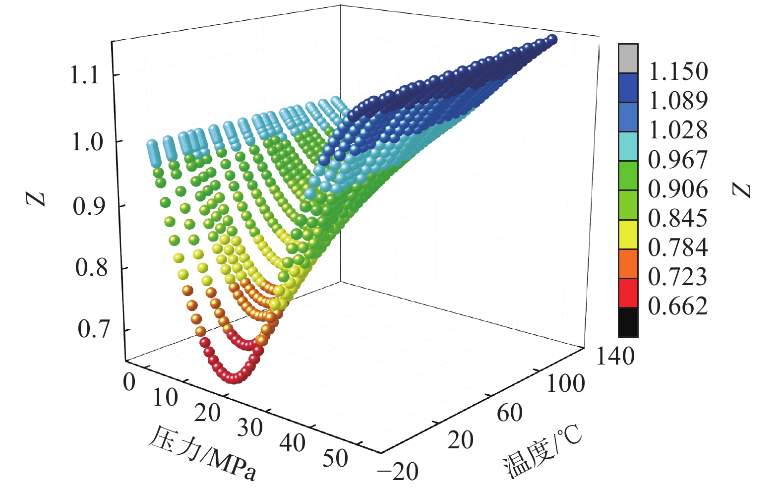
图 2 不同温度、压力下甲烷的压缩因子Z变化规律
Figure 2. Compression factor Z of methane under different temperature and pressure
![]()
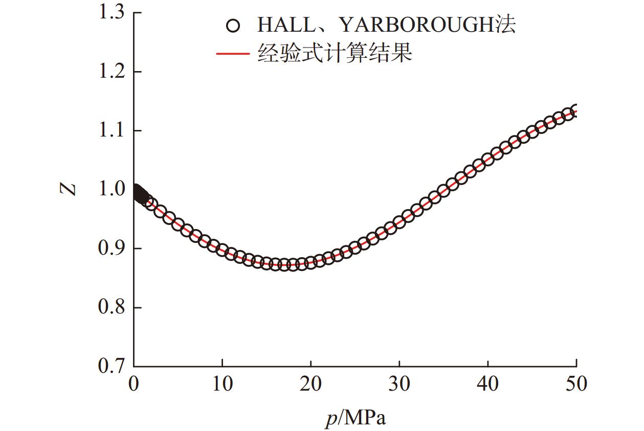
图 3 60 ℃下甲烷的压缩因子Z拟合效果
Figure 3. Fitting effect of methane compression factor Z at 60 ℃
![]()
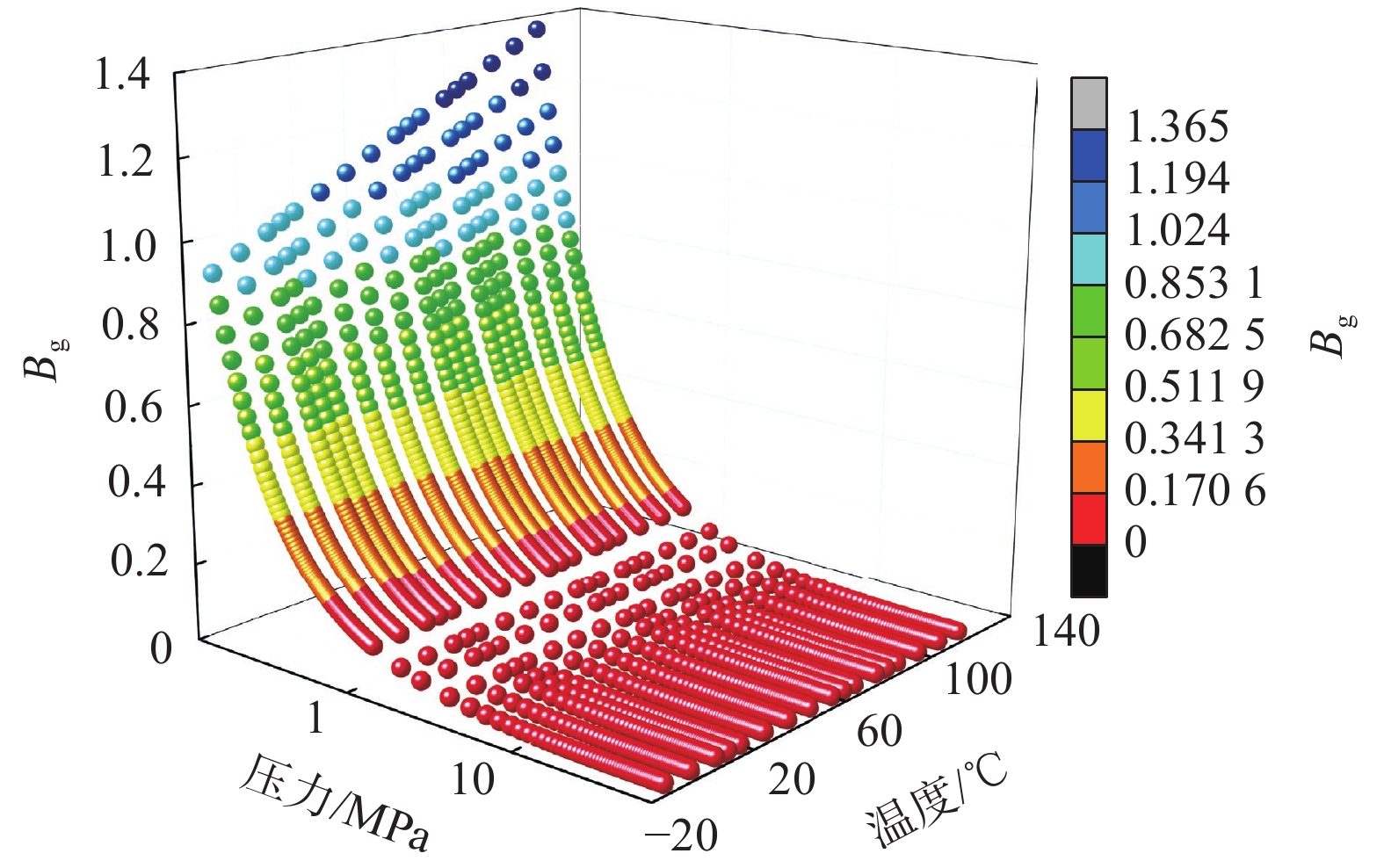
图 4 不同温度压力下的甲烷的体积系数Bg
Figure 4. Volume coefficient Bg of methane under different temperature and pressure
![]()
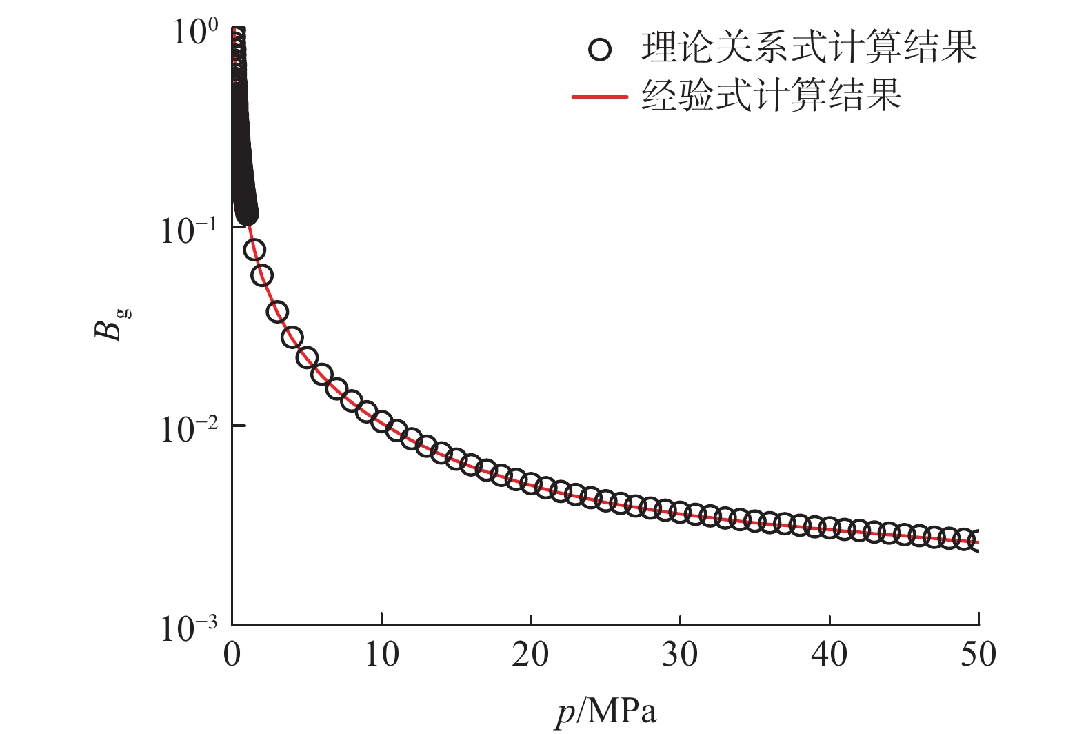
图 5 60 ℃下甲烷的体积系数Bg拟合效果
Figure 5. Fitting effect of methane volume coefficient Bg at 60 ℃
![]()
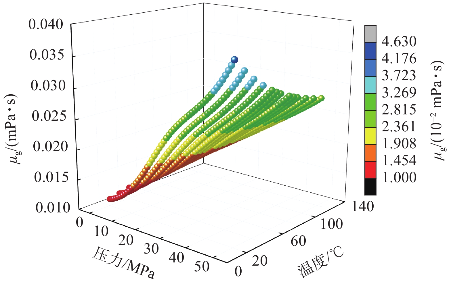
图 6 不同温度压力下的甲烷黏度μg
Figure 6. Methane viscosity μg under different temperature and pressure
![]()
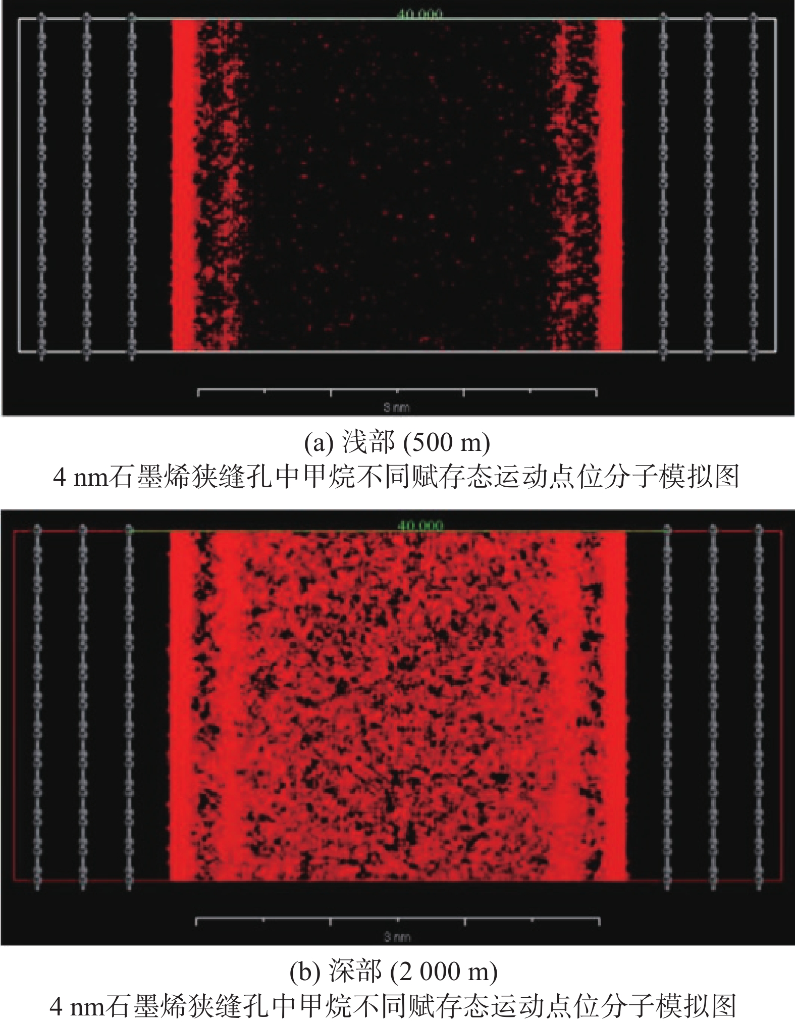
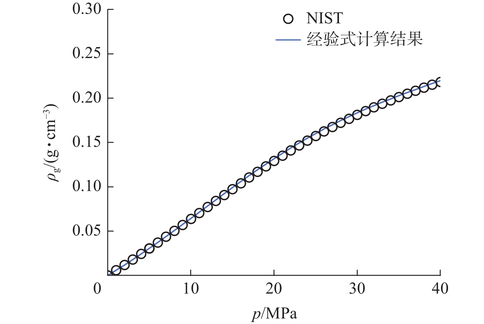
图 9 不同埋深处下的甲烷密度ρg及赋存状态
Figure 9. Occurrence state of methane at different burial depths
![]()
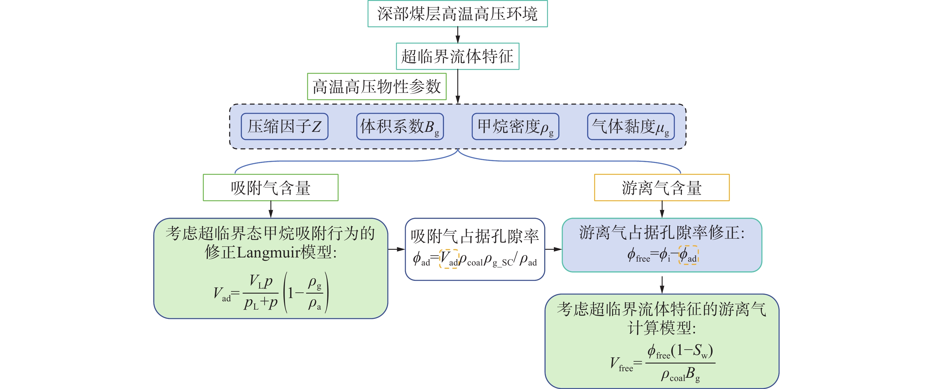
图 11 考虑超临界状态影响的吸附气、游离气含量计算流程
Figure 11. Flowchart for calculating the content of adsorbed gas and free gas considering the influence of supercritical state
![]()
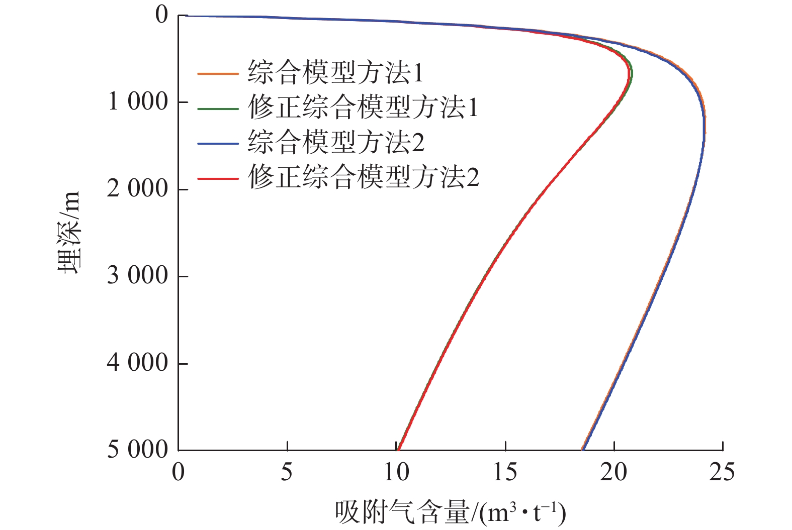
图 12 4种综合模型方法吸附气含量计算结果对比(Ro=2.7%)
Figure 12. Comparison of calculation results of adsorbed gas content by four integrated model methods(Ro=2.7%)
![]()
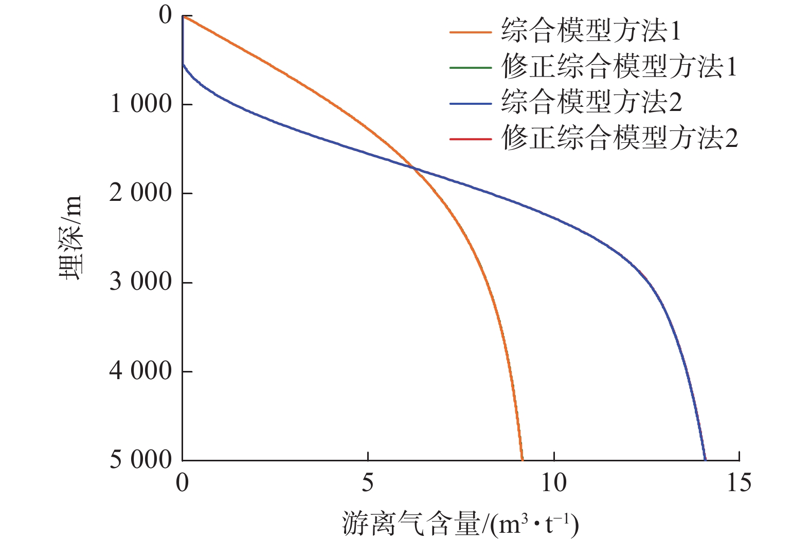
图 13 4种综合模型方法游离气含量计算结果对比(Ro=2.7%)
Figure 13. Comparison of calculation results of free gas content by four comprehensive model methods(Ro=2.7%)
![]()
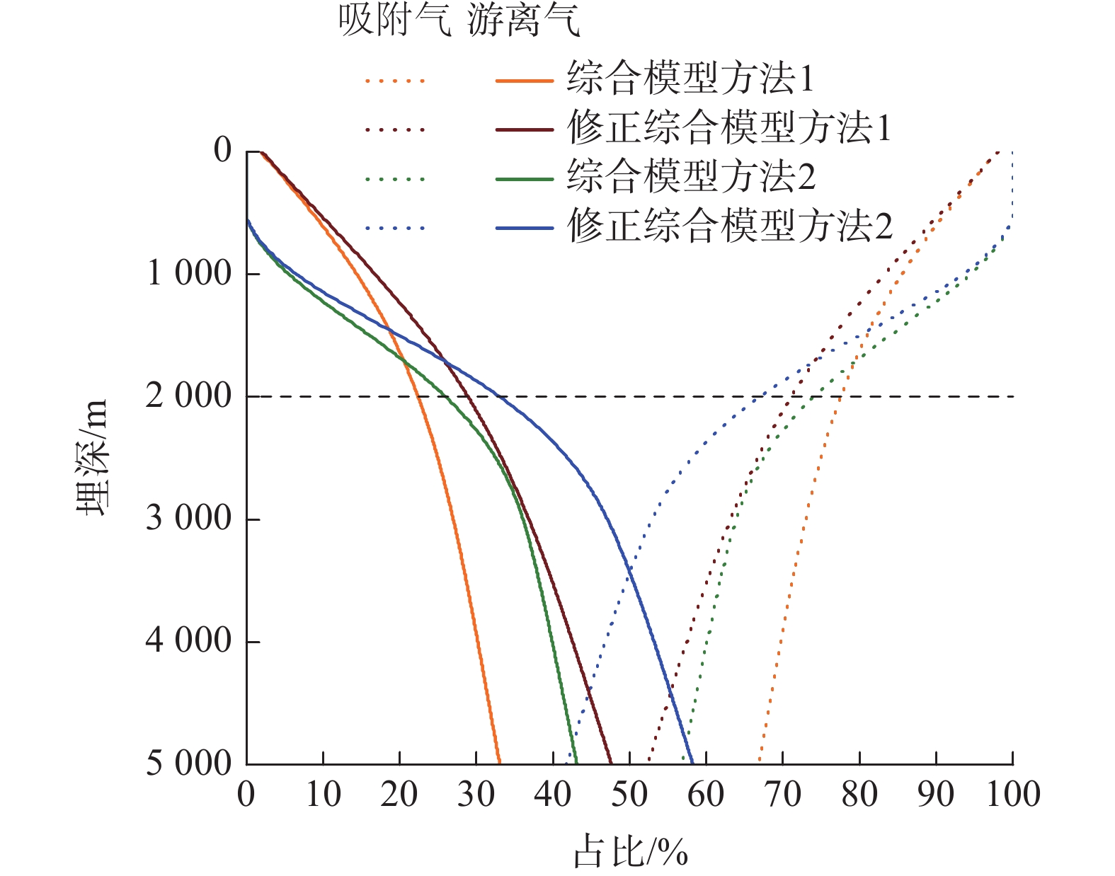
图 14 4种综合模型方法吸附气含量/游离气含量占比随埋深变化曲线(Ro=2.7%)
Figure 14. Four comprehensive model methods adsorbed gas content/free gas content ratio with depth curve(Ro=2.7%)
![]()
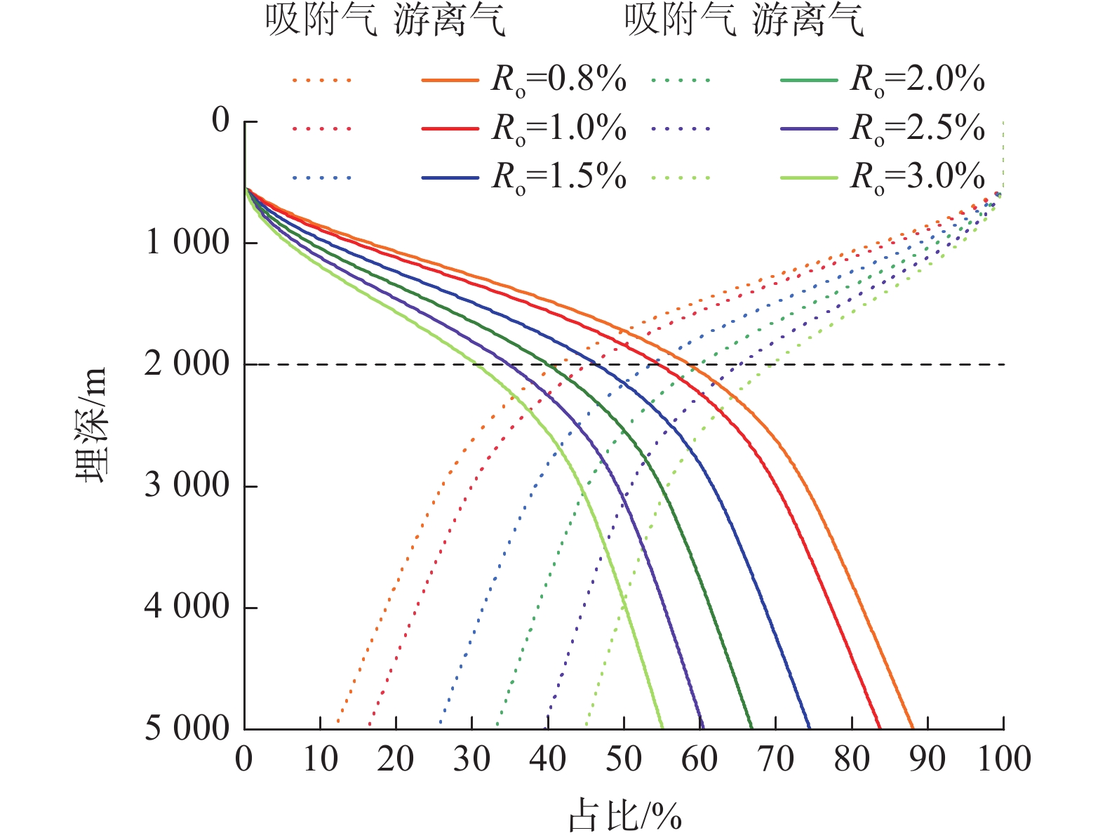
图 15 不同镜质体反射率下的吸附气含量/游离气含量占比随深度变化曲线
Figure 15. Curves of adsorbed gas content/free gas content ratio with depth under different vitrinite reflectance
![]()
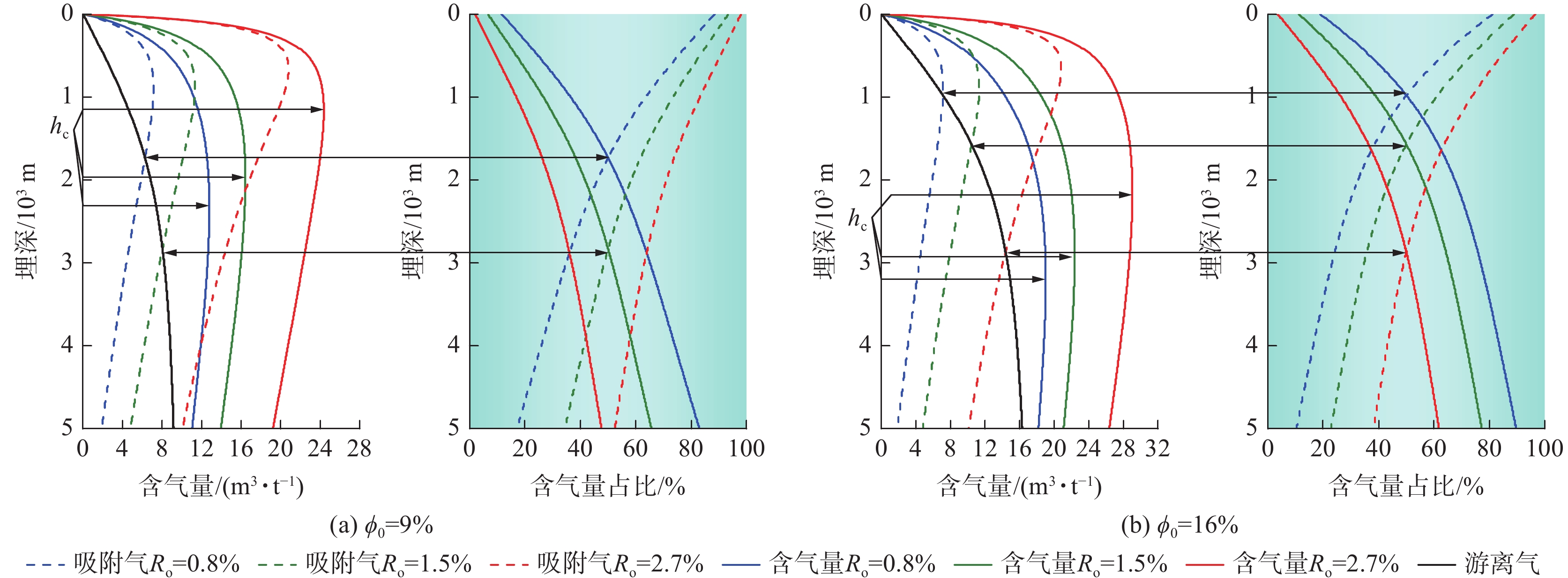
图 16 煤层气不同赋存态含量及占比随埋深、Ro分配规律(修正综合模型方法1(Sw=35%))
Figure 16. Distribution of coalbed methane different occurrence content with different depth and Ro calculated by modified synthesis model method 1 (Sw =35%)
![]()
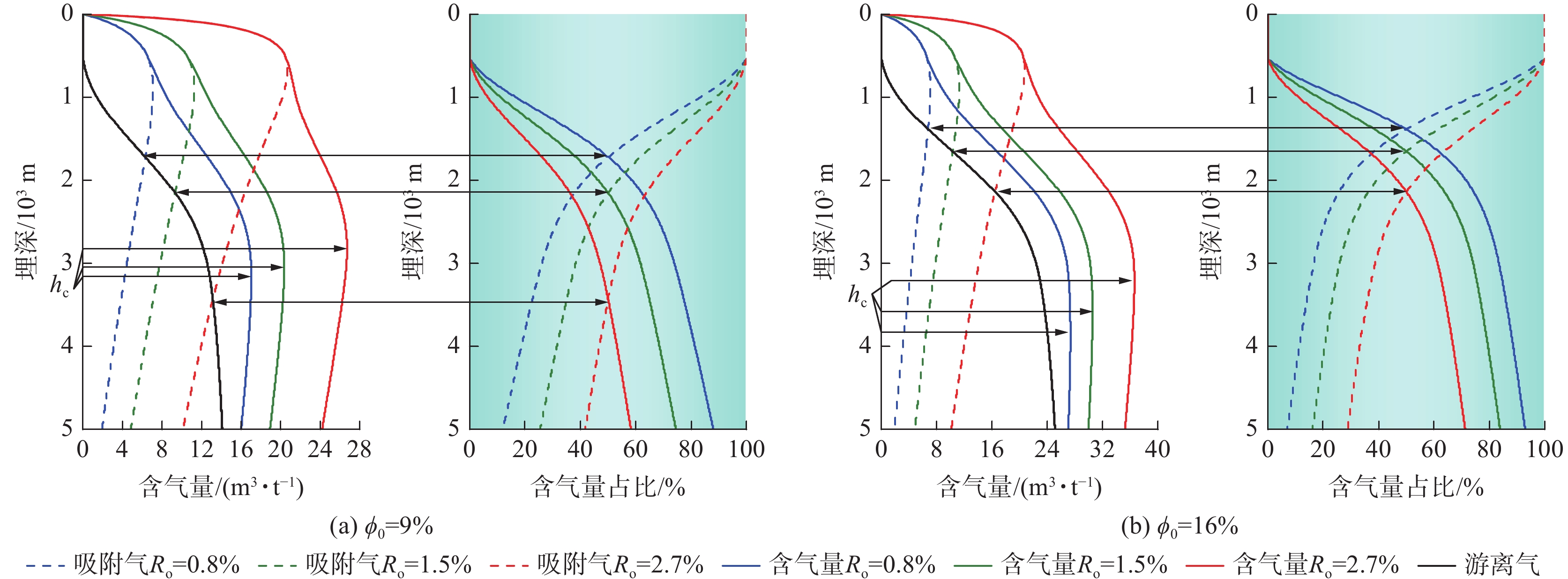
图 17 煤层气不同赋存态含量及占比随埋深、Ro分配规律(修正综合模型方法2 (Sw (h)))
Figure 17. Distribution of coalbed methane different occurrence content with different depth and Ro calculated by modified synthesis model method 2 (Sw (h))
![]()
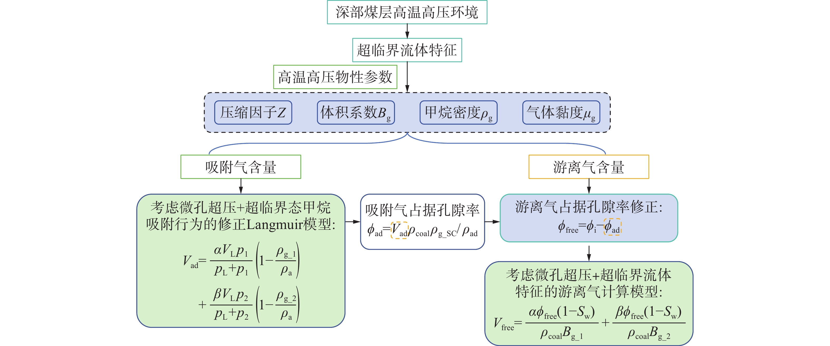
图 18 考虑“微孔超压+超临界状态”影响的吸附气、游离气含量计算流程
Figure 18. Flowchart for calculating the content of adsorbed gas and free gas considering the influence of “microporous overpressure+supercritical state”
![]()
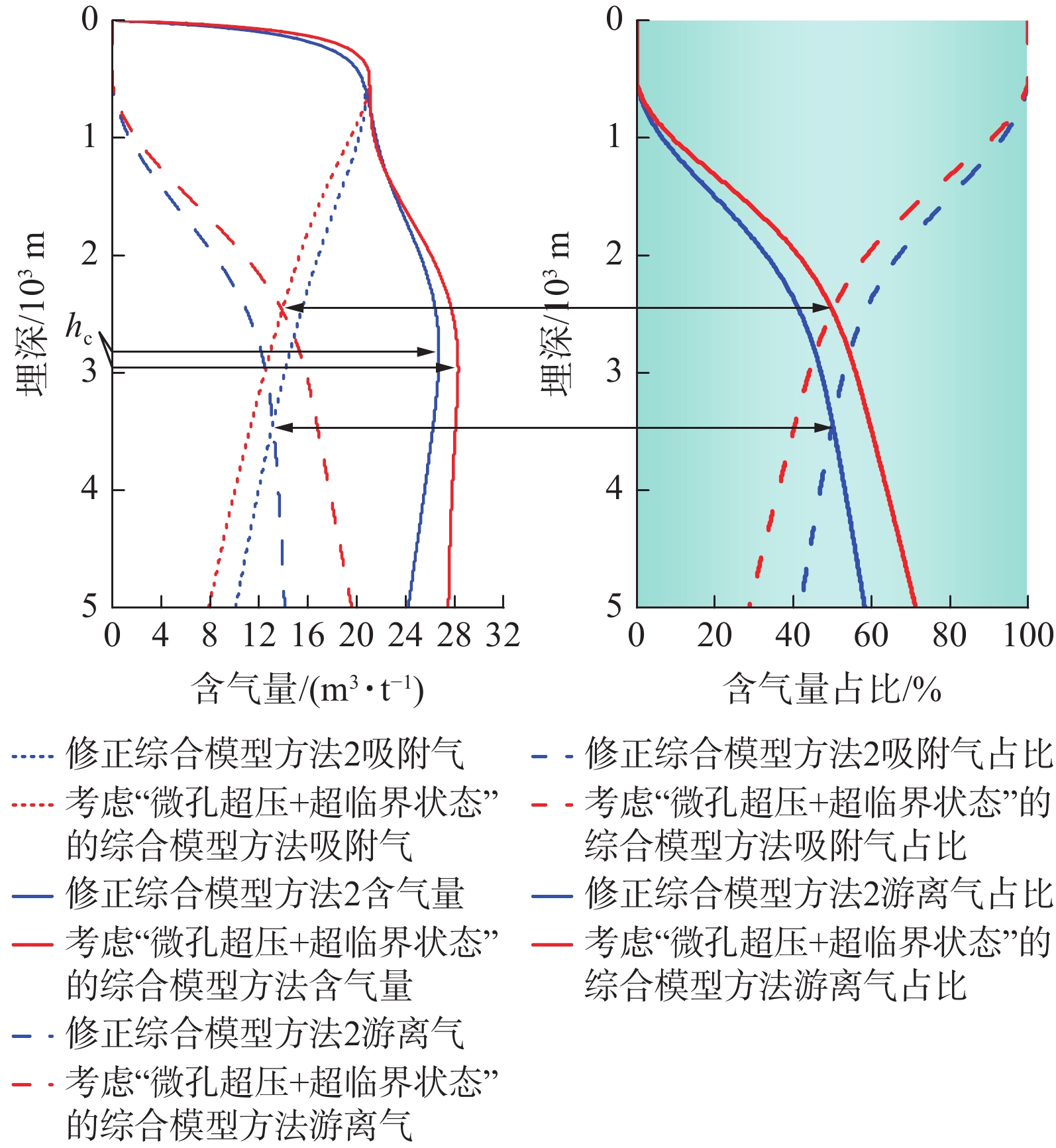
图 19 Ro=2.7%时是否考虑微孔超压对不同相态含量分配规律(在修正综合模型方法2基础上考虑微孔超压,再与修正模型方法2对比)
Figure 19. Distribution law of different phase content and proportion of coalbed methane with buried depth when Ro=2.7%
表 1 不同温度下甲烷的压缩因子Z经验式
Table 1 Empirical formula of compression factor Z for methane at different temperatures
温度/℃ Z经验式 40 $ \begin{gathered} \textit{Z} = {\text{5}}{\text{.178}} \times {10^{ - 9}}{p^5} - {\text{8}}{\text{.417}} \times {10^{ - 7}}{p^4} + {\text{3}}{\text{.923}} \times {10^{ - 5}}{p^3} - \\ {\text{1}}{\text{.554}} \times {10^{ - 4}}{p^2} - {\text{0}}{\text{.014\;9}}p + {\text{0}}{\text{.999\;3}} \\ \end{gathered} $ 50 $ \begin{gathered} \textit{Z} = {\text{4}}{\text{.225}} \times {10^{ - 9}}{p^5} - {\text{6}}{\text{.952}} \times {10^{ - 7}}{p^4} + {\text{3}}{\text{.242}} \times {10^{ - 5}}{p^3} - \\ {\text{9}}{\text{.121}} \times {10^{ - 5}}{p^2} - {\text{0}}{\text{.013\;4}}p + {\text{0}}{\text{.999\;4}} \\ \end{gathered} $ 60 $ \begin{gathered} \textit{Z} = 3.484 \times {10^{ - 9}}{p^5} - 5.791 \times {10^{ - 7}}{p^4} + 2.697 \times {10^{ - 5}}{p^3} - \\ 4.248 \times {10^{ - 5}}{p^2} - 0.012\;0p + 0.999\;5 \\ \end{gathered} $ 70 $ \begin{gathered} \textit{Z} = {\text{2}}{\text{.902}} \times {10^{ - 9}}{p^5} - {\text{4}}{\text{.866}} \times {10^{ - 7}}{p^4} + {\text{2}}{\text{.259}} \times {10^{ - 5}}{p^3} - \\ {\text{5}}{\text{.571}} \times {10^{ - 6}}{p^2} - {\text{0}}{\text{.010\;8}}p + {\text{0}}{\text{.999\;6}} \\ \end{gathered} $ 80 $ \begin{gathered} \textit{Z} = {\text{2}}{\text{.441}} \times {10^{ - 9}}{p^5} - {\text{4}}{\text{.120}} \times {10^{ - 7}}{p^4} + {\text{1}}{\text{.903}} \times {10^{ - 5}}{p^3}+ \\ {\text{ 2}}{\text{.247}} \times {10^{ - 5}}{p^2} - {\text{0}}{\text{.009\;7}}p + {\text{0}}{\text{.999\;7}} \\ \end{gathered} $ 90 $ \begin{gathered} \textit{Z} = {\text{2}}{\text{.072}} \times {10^{ - 9}}{p^5} - {\text{3}}{\text{.516}} \times {10^{ - 7}}{p^4} + {\text{1}}{\text{.613}} \times {10^{ - 5}}{p^3}+ \\ {\text{4}}{\text{.357}} \times {10^{ - 5}}{p^2} - {\text{0}}{\text{.008\;7}}p + {\text{0}}{\text{.999\;7}} \\ \end{gathered} $  下载: 导出CSV
表 2 常用温度、压力下甲烷的压缩因子Z取值
Table 2 Compression factor Z value of methane under common temperature and pressure
压力/MPa 40 ℃ 50 ℃ 60 ℃ 70 ℃ 80 ℃ 90 ℃ 0.101 0.998354 0.998531 0.998689 0.998829 0.998954 0.999066 0.2 0.996744 0.997096 0.997408 0.997686 0.997933 0.998155 0.4 0.993504 0.994208 0.994832 0.995387 0.995882 0.996325 0.6 0.990279 0.991336 0.992273 0.993106 0.993847 0.99451 0.8 0.987071 0.988481 0.989731 0.99084 0.991829 0.992712 1 0.98388 0.985644 0.987206 0.988592 0.989827 0.990929 5 0.924544 0.933239 0.940878 0.947618 0.953585 0.958885 10 0.867232 0.88328 0.89735 0.909738 0.920685 0.930394 20 0.834538 0.856567 0.876064 0.893372 0.90878 0.92253 30 0.916243 0.931033 0.944678 0.957241 0.968789 0.97939 40 1.0417 1.0464 1.05134 1.05639 1.06144 1.06641
下载: 导出CSV
表 3 常用温度、压力下甲烷的体积系数Bg取值
Table 3 Volume coefficient Bg value of methane under common temperature and pressure
压力/MPa 40 ℃ 50 ℃ 60 ℃ 70 ℃ 80 ℃ 90 ℃ 0.101 1.08493 1.11978 1.15461 1.18944 1.22425 1.25906 0.2 0.547008 0.564675 0.582332 0.599978 0.617616 0.635245 0.4 0.272615 0.28152 0.290414 0.299298 0.308173 0.31704 0.6 0.181153 0.187138 0.193111 0.199075 0.205029 0.210975 0.8 0.135425 0.139949 0.144462 0.148965 0.153459 0.157945 1 0.10799 0.111638 0.115275 0.118902 0.12252 0.126129 5 0.020295 0.021141 0.021973 0.022795 0.023607 0.02441 10 0.009519 0.010004 0.010478 0.010942 0.011396 0.011842 20 0.00458 0.004851 0.005115 0.005372 0.005624 0.005871 30 0.003352 0.003515 0.003677 0.003838 0.003997 0.004155 40 0.002858 0.002963 0.003069 0.003176 0.003285 0.003393
下载: 导出CSV
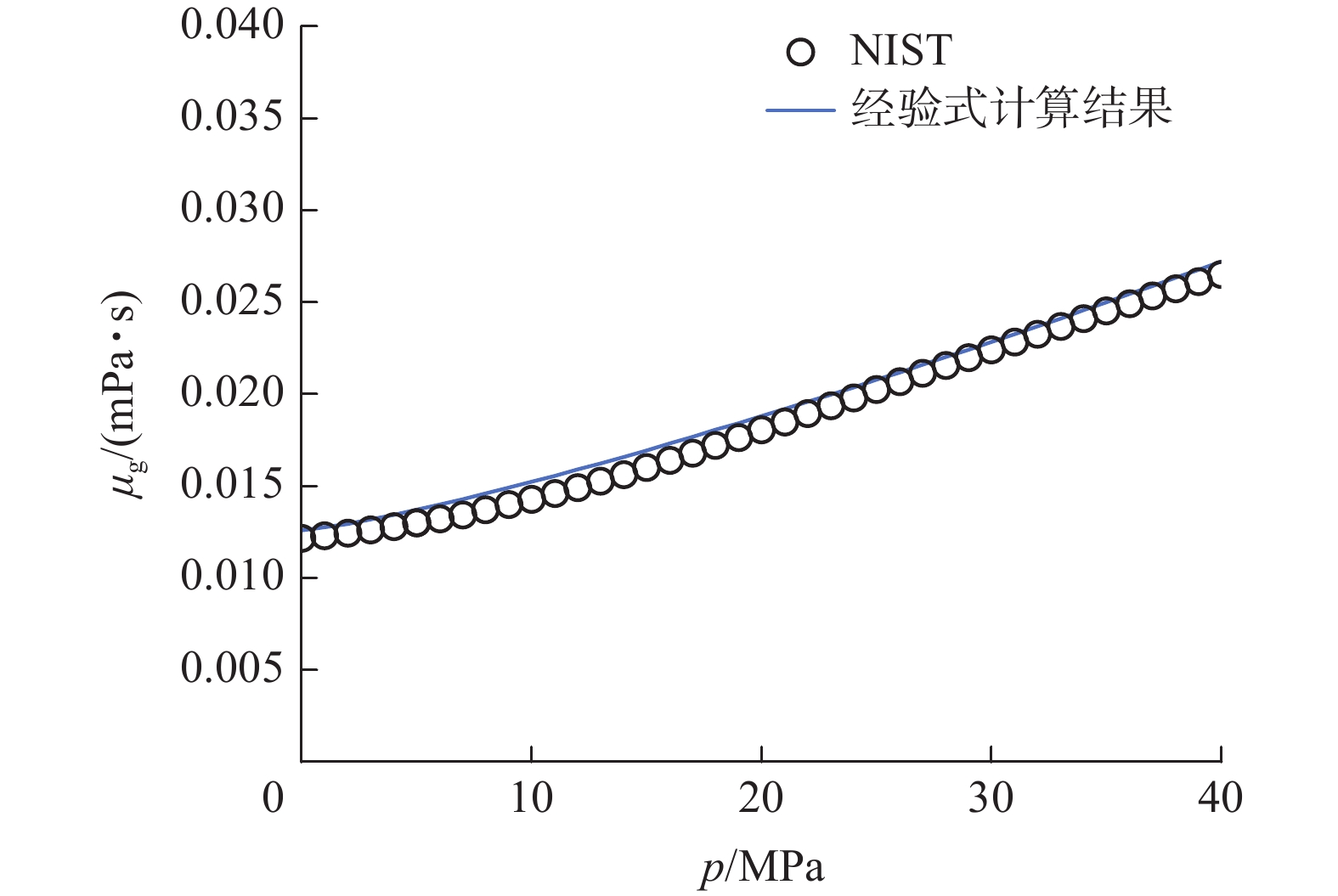
表 4 不同温度下甲烷黏度μg经验式
Table 4 Empirical formula of methane viscosity μg at different temperatures
温度/℃ 气体黏度μg经验式 40 $ {\mu _{\text{g}}} = 0.012\;2 - {\text{1}}{\text{.780}} \times {10^{ - 4}}{p^{{\text{1}}{\text{.215}}}} $ 50 $ {\mu _{\text{g}}} = {\text{0}}{\text{.012\;3}} - 1.{\text{781}} \times {10^{ - 4}}{p^{{\text{1}}{\text{.216}}}} $ 60 $ {\mu _{\text{g}}} = 0.012\;6 - {\text{1}}{\text{.534}} \times {10^{ - 4}}{p^{{\text{1}}{\text{.235}}}} $ 70 $ {\mu _{\text{g}}} = 0.013 - 1.344 \times {10^{ - 4}}{p^{1.252}} $ 80 $ {\mu _{\text{g}}} = 0.013 - 1.195 \times {10^{ - 4}}{p^{{\text{1}}{\text{.265}}}} $ 90 $ {\mu _{\text{g}}} = 0.014 - 1.08 \times {10^{ - 4}}{p^{1.276}} $
下载: 导出CSV
表 5 常用温度、压力下甲烷黏度μg取值
Table 5 Methane viscosity μg value of methane under common temperature and pressure
mPa·s 压力/MPa 40 ℃ 50 ℃ 60 ℃ 70 ℃ 80 ℃ 90 ℃ 0.101 0.011916 0.012286 0.012653 0.013017 0.013378 0.013736 0.2 0.011924 0.012294 0.01266 0.013024 0.013384 0.013741 0.4 0.011944 0.012312 0.012677 0.013039 0.013398 0.013755 0.6 0.011967 0.012334 0.012697 0.013058 0.013415 0.013771 0.8 0.011993 0.012357 0.012719 0.013078 0.013434 0.013788 1 0.01202 0.012383 0.012742 0.0131 0.013455 0.013808 5 0.012842 0.013145 0.013453 0.013765 0.014079 0.014395 10 0.014474 0.014637 0.014827 0.015038 0.015265 0.015505 20 0.019407 0.019053 0.018823 0.018686 0.018622 0.018614 30 0.024525 0.023772 0.02319 0.022742 0.022402 0.02215 40 0.028777 0.027887 0.027145 0.026531 0.026024 0.025609
下载: 导出CSV
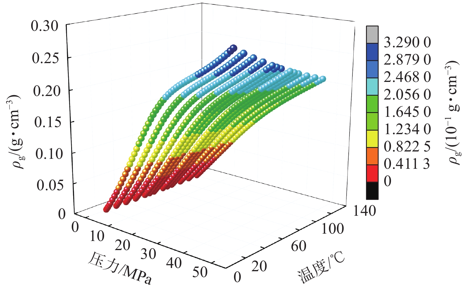
表 6 常用温度、压力下甲烷密度ρg取值
Table 6 Methane density ρg value of methane under common temperature and pressure
g·cm−3 压力/MPa 40 ℃ 50 ℃ 60 ℃ 70 ℃ 80 ℃ 90 ℃ 0.101 0.00062 0.00060 0.00058 0.00057 0.00055 0.00053 0.2 0.00124 0.00120 0.001166 0.001131 0.00109 0.00106 0.4 0.00249 0.00241 0.00233 0.00226 0.00220 0.00214 0.6 0.00374 0.00363 0.00351 0.00340 0.00331 0.00321 0.8 0.00501 0.00485 0.00469 0.00455 0.00442 0.00429 1 0.00628 0.00608 0.00588 0.00570 0.00554 0.00538 5 0.03344 0.03211 0.03089 0.02977 0.02875 0.02780 10 0.07130 0.06784 0.06477 0.06203 0.05955 0.05731 20 0.14820 0.13992 0.13270 0.12633 0.12067 0.11560 30 0.20247 0.19309 0.18459 0.17686 0.16980 0.16334 40 0.23745 0.22907 0.22115 0.21368 0.20664 0.20001
下载: 导出CSV
表 7 4种综合模型方法的考虑因素
Table 7 Two integrated model approaches consider factors
考虑因素 综合模型方法1 修正综合模型方法1 综合模型方法2 修正综合模型方法2 高压物性参数(超临界流体特征) √ √ √ √ 储层应力敏感性 √ √ √ √ 吸附气对孔隙的占据 √ √ √ √ VL(Ro、T、Sw) √ √ √ √ PL(Ro、T、Sw) √ √ √ √ 考虑超临界态甲烷吸附行为的Langmuir吸附模型修正 × √ × √ Sw(h)随埋深变化 × × √ √
下载: 导出CSV
表 8 煤层气储量/含量预测参数取值
Table 8 Parameter value of CBM reserve/content prediction parameter
参数 取值 地面压力pground/MPa 0.016 地面温度Tground/℃ 20 平均储层压力梯度/(MPa·m−1) 0.0098 平均储层温度梯度/(℃·m−1) 0.027 热膨胀系数C1/(10−3 ℃−1) 2.5[36] 常温下甲烷沸点密度ρb/(g·cm−3) 0.423 初始孔隙率ϕ0/% 9 吸附态密度ρa/(g·cm−3) 0.421 煤岩视密度ρcoal/(g·cm−3) 1.3
下载: 导出CSV
表 9 4种综合模型方法得到的不同镜质体反射率下2 000 m处吸附气含量/游离气含量占比
Table 9 Ratio of adsorbed gas content to free gas content at 2 000 m under different vitrinite reflectance obtained by four comprehensive model methods
镜质体反射率Ro/% 0.8 1.5 2.7 综合模型方法1 吸附气含量占比/% 54.61 66.30 77.55 游离气含量占比/% 45.39 33.70 22.45 修正综合模型方法1 吸附气含量占比/% 46.13 58.33 71.08 游离气含量占比/% 53.87 41.67 28.92 综合模型方法2 吸附气含量占比/% 49.79 61.83 73.98 游离气含量占比/% 50.21 38.17 26.02 修正综合模型方法2 吸附气含量占比/% 41.38 53.55 66.92 游离气含量占比/% 58.62 46.45 33.08
下载: 导出CSV
-
[1] 吴裕根,门相勇,娄钰. 我国“十四五” 煤层气勘探开发新进展与前景展望[J]. 中国石油勘探,2024,29(1):1−13. WU Yugen,MEN Xiangyong,LOU Yu. New progress and prospect of coalbed methane exploration and development in China during the 14th Five-Year Plan period[J]. China Petroleum Exploration,2024,29(1):1−13.
[2] 丛日超,王海柱,李根生,等. 超临界CO2聚能压裂开发煤层气可行性研究[J]. 煤炭学报,2023,48(8):3162−3171. CONG Richao,WANG Haizhu,LI Gensheng,et al. Feasibility on exploitation of coalbed methane by SC-CO2 shock fracturing[J]. Journal of China Coal Society,2023,48(8):3162−3171.
[3] 徐凤银,闫霞,林振盘,等. 我国煤层气高效开发关键技术研究进展与发展方向[J]. 煤田地质与勘探,2022,50(3):1−14. XU Fengyin,YAN Xia,LIN Zhenpan,et al. Research progress and development direction of key technologies for efficient coalbed methane development in China[J]. Coal Geology & Exploration,2022,50(3):1−14.
[4] 徐凤银,闫霞,李曙光,等. 鄂尔多斯盆地东缘深部(层)煤层气勘探开发理论技术难点与对策[J]. 煤田地质与勘探,2023,51(1):115−130. XU Fengyin,YAN Xia,LI Shuguang,et al. Theoretical and technological difficulties and countermeasures of deep CBM exploration and development in the eastern edge of Ordos Basin[J]. Coal Geology & Exploration,2023,51(1):115−130.
[5] 闫霞,徐凤银,聂志宏,等. 深部微构造特征及其对煤层气高产 “甜点区” 的控制:以鄂尔多斯盆地东缘大吉地区为例[J]. 煤炭学报,2021,46(8):2426−2439. YAN Xia,XU Fengyin,NIE Zhihong,et al. Microstructure characteristics of Daji area in east Ordos Basin and its control over the high yield dessert of CBM[J]. Journal of China Coal Society,2021,46(8):2426−2439.
[6] 闫霞,熊先钺,李曙光,等. 深层煤岩气水平井各段产出贡献及其主控因素:以鄂尔多斯盆地东缘大宁—吉县区块为例[J]. 天然气工业,2024,44(10):80−92. YAN Xia,XIONG Xianyue,LI Shuguang,et al. Production contributions of deep CBM horizontal well sections and their controlling factors:A case study of Daning–Jixian area,eastern Ordos Basin[J]. 2024,44(10):80−92.
[7] 聂志宏,徐凤银,时小松,等. 鄂尔多斯盆地东缘深部煤层气开发先导试验效果与启示[J]. 煤田地质与勘探,2024,52(2):1−12. NIE Zhihong,XU Fengyin,SHI Xiaosong,et al. Outcomes and implications of pilot tests for deep coalbed methane production on the eastern margin of the Ordos Basin[J]. Coal Geology & Exploration,2024,52(2):1−12.
[8] 赵喆,徐旺林,赵振宇,等. 鄂尔多斯盆地石炭系本溪组煤岩气地质特征与勘探突破[J]. 石油勘探与开发,2024,51(2):234−247,259. ZHAO Zhe,XU Wanglin,ZHAO Zhenyu,et al. Geological characteristics and exploration breakthroughs of coal rock gas in Carboniferous Benxi Formation,Ordos Basin,NW China[J]. Petroleum Exploration and Development,2024,51(2):234−247,259.
[9] 刘建忠,朱光辉,刘彦成,等. 鄂尔多斯盆地东缘深部煤层气勘探突破及未来面临的挑战与对策:以临兴—神府区块为例[J]. 石油学报,2023,44(11):1827−1839. LIU Jianzhong,ZHU Guanghui,LIU Yancheng,et al. Breakthrough,future challenges and countermeasures of deep coalbed methane in the eastern margin of Ordos Basin:A case study of Linxing-Shenfu block[J]. Acta Petrolei Sinica,2023,44(11):1827−1839.
[10] 兰浩,杨兆彪,仇鹏,等. 新疆准噶尔盆地白家海凸起深部煤层气勘探开发进展及启示[J]. 煤田地质与勘探,2024,52(2):13−22. LAN Hao,YANG Zhaobiao,CHOU Peng,et al. Exploration and exploitation of deep coalbed methane in the Baijiahai uplift,Junggar Basin:Progress and its implications[J]. Coal Geology & Exploration,2024,52(2):13−22.
[11] 康永尚,闫霞,皇甫玉慧,等. 深部超饱和煤层气藏概念及主要特点[J]. 石油学报,2023,44(11):1781−1790. KANG Yongshang,YAN Xia,HUANGFU Yuhui,et al. Concept and main characteristics of deep oversaturated coalbed methane reservoir[J]. Acta Petrolei Sinica,2023,44(11):1781−1790.
[12] 刘大锰,贾奇锋,蔡益栋. 中国煤层气储层地质与表征技术研究进展[J]. 煤炭科学技术,2022,50(1):196−203. LIU Dameng,JIA Qifeng,CAI Yidong. Research progress on coalbed methane reservoir geology and characterization technology in China[J]. Coal Science and Technology,2022,50(1):196−203.
[13] 傅雪海,许行行,王强,等. 煤层气异常成分的界定、分布及其成因研究进展[J]. 煤炭科学技术,2023,51(1):343−352. FU Xuehai,XU Hanghang,WANG Qiang,et al. Review of research on definition,distribution and causes of abnormal coalbed methane composition[J]. Coal Science and Technology,2023,51(1):343−352.
[14] 杨兆彪,秦勇,高弟,等. 超临界条件下煤层甲烷视吸附量、真实吸附量的差异及其地质意义[J]. 天然气工业,2011,31(4):13−16,122. YANG Zhaobiao,QIN Yong,GAO Di,et al. Differences between apparent and true adsorption quantity of coalbed methane under supercritical conditions and their geological significance[J]. Natural Gas Industry,2011,31(4):13−16,122.
[15] 赵军龙,池佳玮. 煤层气储层物性影响因素和预测方法综述与展望[J]. 地球物理学进展,2020,35(1):272−280. ZHAO Junlong,CHI Jiawei. Review and prospect of influencing factors andpredictionmethods of coalbedgasreservoirphysicalproperties[J]. Progress in Geophysics,2020,35(1):272−280.
[16] 张新宾,宋党育,李云波,等. 超临界态甲烷密度研究[J]. 煤田地质与勘探,2021,49(1):137−142,150. ZHANG Xinbin,SONG Dangyu,LI Yunbo,et al. Study on density of the supercritical methane[J]. Coal Geology & Exploration,2021,49(1):137−142,150.
[17] 张明杰,刘浩,贾天让,等. 颗粒煤超临界态甲烷吸附相密度特征研究[J]. 煤田地质与勘探,2021,49(5):105−113. ZHANG Mingjie,LIU Hao,JIA Tianrang,et al. Adsorption phase density characteristicsofsupercriticalmethane of granular coal[J]. Coal Geology & Exploration,2021,49(5):105−113.
[18] 刘鹏,刘雅东. 煤层气储量预测方法分析[J]. 内江科技,2012,33(4):29,37. LIU Peng,LIU Yadong. Analysis of Prediction Methods for Coalbed Methane Reserves [J]. Neijiang Science & Technology,2012,33(4):29,37.
[19] ZHANG F,WANG S Z,QIAO M Z,et al. Experiment and simulation assessment of supercritical underground coal gasification in deep coal seam[J]. International Journal of Hydrogen Energy,2024,79:974−985. doi: 10.1016/j.ijhydene.2024.07.075
[20] 桑树勋,牛庆合,曹丽文,等. 深部煤层CO2注入煤岩力学响应特征及机理研究进展[J]. 地球科学,2022,47(5):1849−1864. SANG Shuxun,NIU Qinghe,CAO Liwen,et al. Mechanical response characteristics and mechanism of coal-rock with CO2 injection in deep coal seam:A review[J]. Earth Science,2022,47(5):1849−1864.
[21] ZHANG Z T,ZHANG R,XIE H P,et al. The relationships among stress,effective porosity and permeability of coal considering the distribution of natural fractures:Theoretical and experimental analyses[J]. Environmental Earth Sciences,2015,73(10):5997−6007. doi: 10.1007/s12665-015-4280-3
[22] TANG X,RIPEPI N,RIGBY S,et al. New perspectives on supercritical methane adsorption in shales and associated thermodynamics[J]. Journal of Industrial and Engineering Chemistry,2019,78:186−197. doi: 10.1016/j.jiec.2019.06.015
[23] LI C,QIN Y,GUO T,et al. Supercritical methane adsorption in coal and implications for the occurrence of deep coalbed methane based on dual adsorption modes[J]. Chemical Engineering Journal,2023,474:145931. doi: 10.1016/j.cej.2023.145931
[24] HALL K R,YARBOROUGH L. A new equation of state for Z-factor calculations[J]. Oil and Gas Journal,1973,71(25):82−92.
[25] YARBOROUGH L,HALL K R. How to solve equation of state for Z-factors[J]. Oil and Gas Journal,1974,72(7):86−88.
[26] LEE A L,GONZALEZ M H,EAKIN B E. The viscosity of natural gases[J]. Journal of Petroleum Technology,1966,18(8):997−1000. doi: 10.2118/1340-PA
[27] The National Institute of Standards and Technology (NIST). Thermophysical properties of fluid systems[EB/OL]. [2024−02−01]. http://webbook. nist.gov/chemistry/fluid/.
[28] 周尚文,薛华庆,郭伟,等. 页岩气超临界吸附研究进展[J]. 科技导报,2017,35(15):63−69. ZHOU Shangwen,XUE Huaqing,GUO Wei,et al. Progress and prospect in supercritical adsorption of shale gas[J]. Science & Technology Review,2017,35(15):63−69.
[29] ZHOU Y,XIE Y G,WANG J L,et al. Density analysis of adsorption phase in the thermodynamic study of shale gas adsorption[J]. Langmuir,2024,40(16):8593−8607. doi: 10.1021/acs.langmuir.4c00293
[30] 郑超,马东民,陈跃,等. 水分对煤层气吸附/解吸微观作用研究进展[J]. 煤炭科学技术,2023,51(2):256−268. ZHENG Chao,MA Dongmin,CHEN Yue,et al. Research progress micro effect of water on coalbed methane adsorption/desorption[J]. Coal Science and Technology,2023,51(2):256−268.
[31] 邓泽,王红岩,姜振学,等. 深部煤储层孔裂隙结构对煤层气赋存的影响:以鄂尔多斯盆地东缘大宁—吉县区块为例[J]. 煤炭科学技术,2024,52(8):106−123. DENG Ze,WANG Hongyan,JIANG Zhenxue,et al. Influence of deep coal pore and fracture structure on occurrence of coalbed methane:A case study of Daning-Jixian Block in eastern margin of Ordos Basin[J]. Coal Science and Technology,2024,52(8):106−123.
[32] 唐淑玲,汤达祯,杨焦生,等. 鄂尔多斯盆地大宁—吉县区块深部煤储层孔隙结构特征及储气潜力[J]. 石油学报,2023,44(11):1854−1866,1902. TANG Shuling,TANG Dazhen,YANG Jiaosheng,et al. Pore structure characteristics and gas storage potential of deep coal reservoirs in Daning-Jixian block of Ordos Basin[J]. Acta Petrolei Sinica,2023,44(11):1854−1866,1902.
[33] 杨兆彪,李存磊,郭巧珍,等. 新疆准噶尔盆地白家海凸起深部煤层气不同赋存态分配规律[J]. 中国矿业大学学报,2025,54(1):127−137. YANG Zhaobiao,LI Cunlei,GUO Qiaozhen,et al. Distribution patterns of various occurrence states of deep coalbed methane in the Baijiahai Uplift,Junggar Basin,Xinjiang[J]. Journal of China University of Mining & Technology,2025,54(1):127−137.
[34] LUCIER A M,HOFMANN R,BRYNDZIA L T. Evaluation of variable gas saturation on acoustic log data from the Haynesville Shale gas play,NW Louisiana,USA[J]. The Leading Edge,2011,30(3):300−311. doi: 10.1190/1.3567261
[35] 李勇,高爽,吴鹏,等. 深部煤层气游离气含量预测模型评价与校正:以鄂尔多斯盆地东缘深部煤层为例[J]. 石油学报,2023,44(11):1892−1902. LI Yong,GAO Shuang,WU Peng,et al. Evaluation and correction of prediction model for free gas content in deep coalbed methane:A case study of deep coal seams in the eastern margin of Ordos Basin[J]. Acta Petrolei Sinica,2023,44(11):1892−1902.
[36] OZAWA S,KUSUMI S,OGINO Y. Physical adsorption of gases at high pressure. IV. An improvement of the Dubinin:Astakhov adsorption equation[J]. Journal of Colloid and Interface Science,1976,56(1):83−91. doi: 10.1016/0021-9797(76)90149-1
[37] LI C L,YANG Z B,YAN X,et al. Distribution law of occurrence state and content prediction of deep CBM:A case study in the Ordos basin,China[J]. Natural Resources Research,2024,33(4):1843−1869. doi: 10.1007/s11053-024-10367-9
[38] 杨焦生,冯鹏,唐淑玲,等. 大宁—吉县区块深部煤层气相态控制因素及含量预测模型[J]. 石油学报,2023,44(11):1879−1891. YANG Jiaosheng,FENG Peng,TANG Shuling,et al. Phase control factors and content prediction model of deep coalbed methane in Daning-Jixian block[J]. Acta Petrolei Sinica,2023,44(11):1879−1891.
[39] 刘程瑞. 煤储层纳米级微孔超压环境形成机制研究[D]. 焦作:河南理工大学,2021. LIU Chengrui. Study on the formation mechanism of overpressure environment of nanoscale micro-pores in coal reservoir [D]. Jiaozuo:Henan Polytechnic University,2021.
[40] 宋金星,苏现波,王乾,等. 考虑微孔超压环境的煤储层含气量计算方法[J]. 天然气工业,2017,37(2):19−25. SONG Jinxing,SU Xianbo,WANG Qian,et al. A new method for calculating gas content of coal reservoirs withconsideration of a micro-pore overpressure environment[J]. Natural Gas Industry,2017,37(2):19−25.
[41] 宋金星,刘玉芳,王乾. 煤系气储层微孔超压理论及应用[M]. 北京:化学工业出版社,2022. [42] 闫霞,徐凤银,熊先钺,等. 深部煤层气勘探开发关键实验技术及发展方向[J]. 煤田地质与勘探,2025,53(1):128−141. YAN Xia,XU Fengyin,XIONG Xianyue,et al. Key experimental technologies and their development directions for the exploration and production of deep coalbed methane[J]. Coal Geology & Exploration,2025,53(1):128−141.
-
期刊类型引用(0)
其他类型引用(1)


计量
- 文章访问数: 320
- HTML全文浏览量: 62
- PDF下载量: 173
- 被引次数: 1
